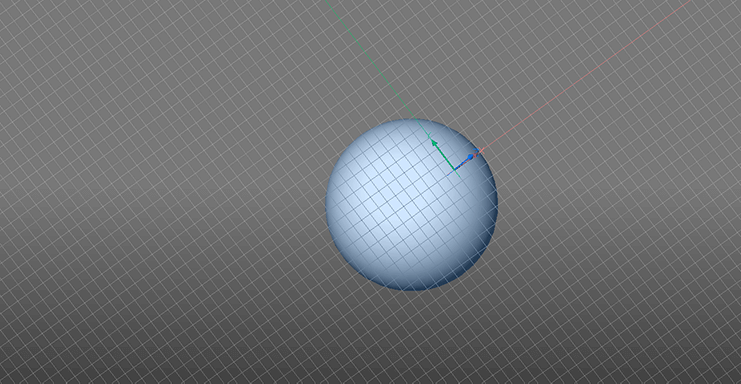
User-defined x,y-planes. UCS, DUCS and UCSORTHO. We take a look at the many ways you can manipulate your drawing planes with BricsCAD.
Static Usr Coordinate System
The "slow way"
To set Static User Coordinate System (UCS) enter UCS in the command line. You will get a range of options. Once the new cordinate system is set you can draw anywhere along this plane with 2D polylines, shapes or 3D objects.
With Face, you can set the coordinate system to any given face.

When the coordinate system is set to a given plane draw along this axis at any point.
The View option will align the drawing plane with whatever the current view is. This does not follow the view. You can rotate the view and remain drawing at the origonal angle.
There are also options to move the view to the x, y, and z axes or to a known point, with X/Y/Z/Z Axis.
With Move you can change the user coordinate system to any given point on the view panel.
Use Entity to align the cordinate system along any 2D object. This can be really handy when drawing in 2D.

The red lign shows how BricsCAD automatically detects the axis of a given object and changes the user cordinate system to fit.
It's worth noting that the default views auto-align with the new coordinate system.
Use World to reset the drawing plane to the default position.
Dynamic User Coordinate System
The "fast way"
When DUCS [F6] is switched on, the drawing plane automatically aligns to a surface when a command is in progress.
To keep a given drawing plane active, hit shift and the target surface will turn blue. The drawing plane will remain set to this face for the duration of the current command. It will will then return to the default setting.

Hit shift to set the DUCS during a given command, the face will turn blue when selected.
Orthographic User Coordinate System
Orthographic User Coordinate System (UCSORTHO). This is where things start to get really interesting! If you go into the settings and check the UCSORTHO box, you can have a drawing plane that changes with your given view. Which means you draw at whatever angle the active view port is currently set to.
The reason it's so cool is that this means you can use Viewports  VPORTS to create a multi-panel drawing view. Dependent on which view port is active, the drawing plane will auto align. This can be invaluable when drawing from 2D engineering plans.

Use UCSORTHO to change the coordinate system as you change the view port.
Furthermore, each of these view ports can have a different view style, which is also pretty useful!
Combine these techniques

Combine these techniques to quickly create objects that are aligned on a wide range of axes.
Ready to get started?
Easy to try, easy to buy, easy to own. That's BricsCAD. Try all of our products, for free for 30 days at www.bricsys.com. Freedom of choice, plus perpetual (permanent) product licenses that work with all languages, in all places. You'll love what we've built for you with the BricsCAD V19 product family.
Explore BricsCAD
Download BricsCAD Free Trial | Sign Up For News & Updates | Shop Online For BricsCAD Desktop Software


