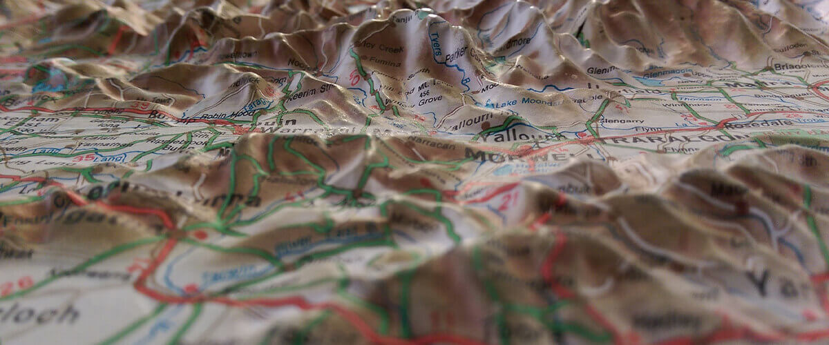
BricsCAD BIM, it works in 3D from the ground up, literally. This week I'm going to show you how to make the most of the SITE commands in BricsCAD BIM.
The SITE tool
BricsCAD BIM uses Triangulated irregular network (TIN) surfaces to create terrains. SITE displays a range of options. You can create TIN surfaces in BricsCAD by importing point data, drawing a range of polylines or placing points one at a time.
Importing
The simplest way of creating a TIN surface is by importing point data. File formats .csv and .txt are both supported. Launch the SITE command, choose Import from file and select the file. That's it. It's that simple!
If your TIN surface doesn't appear, try altering the viewport, you might be too far zoomed in or out.
Constructing with lines and points
This can be useful when you haven't got a coordinate point file. You can create a topographical surface from polylines and/or points.

Example of a topographical surface created with simple polylines
Launch the SITE command, choose select all entities, or manually select entities as required. The topographical surface is then created based on the selected points and polylines.
For the example here I created a simplified, scale version of Hawii. To do this I found a topographic map online and traced it out with SPLINE.
I then changed the altitude and converted the splines to polylines using PE (PEDIT). For more information on Polylines and splines see here.
After that, I simply launched the SITE command, selected all entities and voila.
Placing points
Launch the SITE command and select Place points. Choose your first point and enter the elevation value, continue until the surface is completed. A minimum of three points are needed to create a TIN surface.
Modifying the TIN surface

Top left: number of contour intervals reduced. Bottom left: contour intervals increased. Top right: points only. Bottom right: triangles only.

Once selected, the TIN surface's properties will display in the Properties panel.
TIN Visual style turn contours, triangles, points, and the boundary line, on and off.
TIN settings control the contours; colors and intervals.
TIN stats provides you with all the relevant information regarding your surface.
Site common Add information regarding your maximum building area, including constraints such as height and area. This can be used when exporting your file and works in a similar way to Revit®.
Settings
You can alter the complexity of your TIN surface before you create it in Settings.

Arc approximation mid-ordinate distance determines how complex the surface is when created. The lower the number the higher the accuracy.
Note: it is important to remember that the value of the drawing space will affect the value set. Each BricsCAD template has a different default value dependant on mm, m, inches, etc.

Varying degrees of accuracy when sampling a complex, closed polygon made from curves and straight edges. Left: most accurate. Right: least accurate.
Break lines intersections can be turned on or off. Breakline crossings can be turned off or o. Values of; 0 -- minimum, 1 -- maximum or 2 -- average.

Breakline left to right: none, 1 maximum, 2 average, and 0 minimum
Use SITEEDIT to change individual points, by adding, deleting or moving them.
Use Associativity to set BricsCAD to live update, or not, as you make changes. This can be particularly useful when working with large and complex surfaces. It means that you are able to edit the geometry and then turn Associativity back on to update the model. 0 -- no associativity, 1 -- surface only, 2 -- grading only, 3 -- both.
You can change the boundary of the site, to reduce the working area and help you focus. To do this draw a simple, closed polyline, select Add to Site, select the surface, choose Add b0ndary and select the polygon. You can create a boundary within and outside of the selected polygon. The boundary line can be altered retrospectively.

In this example, I have created a cross-section of the volcanos, But it could just as easily be used to trim down a plot area.
Grading
If you need to level off a topographical surface before building, or maybe add a duck pond, you can! First, draw the shape of the new surface area and then set the elevation. Select Create Grading, entity and then the surface. You can set the angle of grading manually or with the mouse. As with the boundary lines, the grading geometry can be updated after the grading has been created. Be sure to set Associativity to 2 or 3 to update the drawing as you update the geometry.

Here I've gone crazy and shown you what it would look like if they decided to level off the surface between the two peaks of Hawaii. Now that's a wall!
You can also change the accuracy of the grading in Settings -- length sampling interval and Angle sampling interval (the higher this is set the lower the accuracy).

Left: low accuracy grading. Right: High accuracy grading.
What's next?
I've had a word with the developers and I can tell you that BricsCAD is not resting on its laurels. They are already well underway to developing all kinds of cool new features, for the next BricsCAD major release, that will make working with topographical surfaces as fun as playing computer games!
Ready to try BricsCAD BIM V19?
Easy to try, easy to buy, easy to own. That's BricsCAD. Try all of our products, for free for 30 days at www.bricsys.com. Freedom of choice, plus perpetual (permanent) product licenses that work with all languages, in all places. You'll love what we've built for you with the BricsCAD V19 product family.

