How to work with point clouds
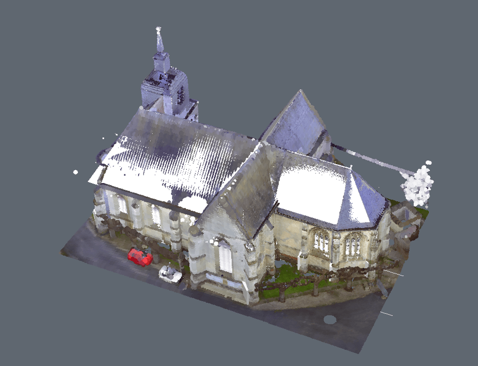
In this series, we will cover how to work with point clouds and how to trace and convert a point cloud to a BIM model. Yes, we will do a manual 'Scan to BIM'. However, the good news is: BricsCAD® is working together with Leica and HOK to fully automate this process. So, within a couple of years, all you'll have to do is click one button! Exciting isn't it?
In this post we are going to look at how to create the external parts of the church: the walls and roof.
Getting Started
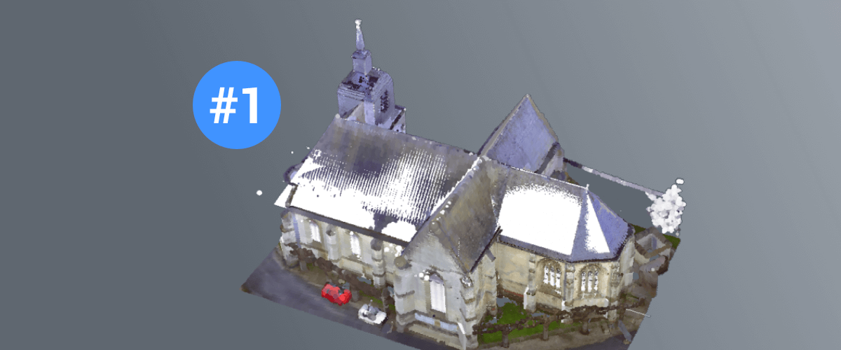
For now let's start by opening a point cloud in BricsCAD, something which is pretty cool in itself! To do this I started in a new, empty file, then I inserted the point cloud and clipped it to the relevant volume.
How to Do This:
- Use PointCloudAttach to attach the point cloud source files to a .dwg file.
Note: You can add following file formats: .las, .pts, .ptx, .rcp, .rcs. - Insert the point cloud at 0,0,0.
Note: the point cloud is immediately loaded and pre-processed at the same time.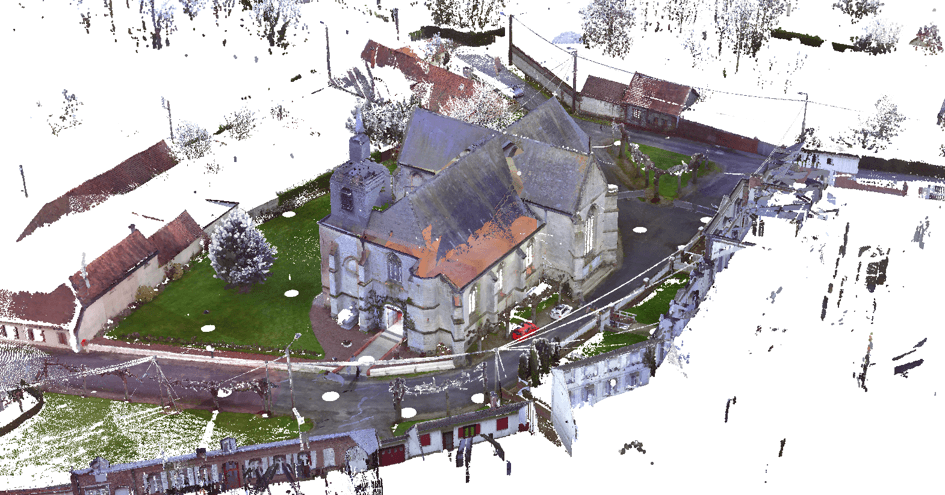
- The point cloud will display (in this instance a church). To work with only a portion of the point cloud file, make a clipping volume. To do this use BIMSection with the Detail option and clip the display so that you can only see the portion of the point cloud that you need (in this case the church).

Tracing the outline
To better see the outline, I made a new slice of the building, then I traced the walls with a Polysolid. The height does not matter, for now, you can adjust it later.
How to Do This
Use BIMSection with the Detail option to make a clipping volume of a slice of the church. Clip the display so that it resembles a plan view:
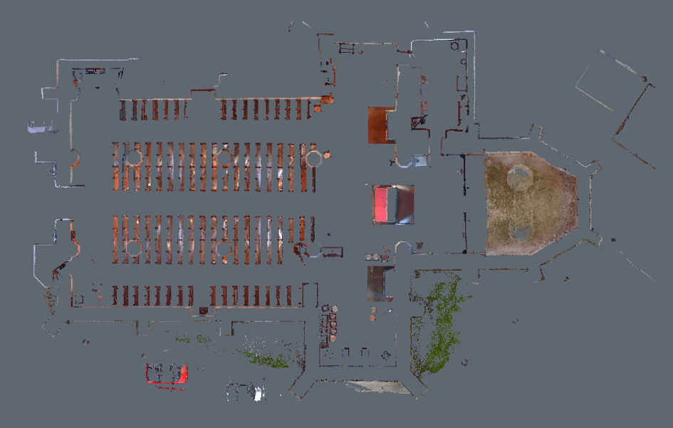
Measure the distance between the points to get the thickness of the wall.
Use Polysolid to draw over the floor plan. Use the thickness from the previous step (in this example: around 1m) as the wall thickness.
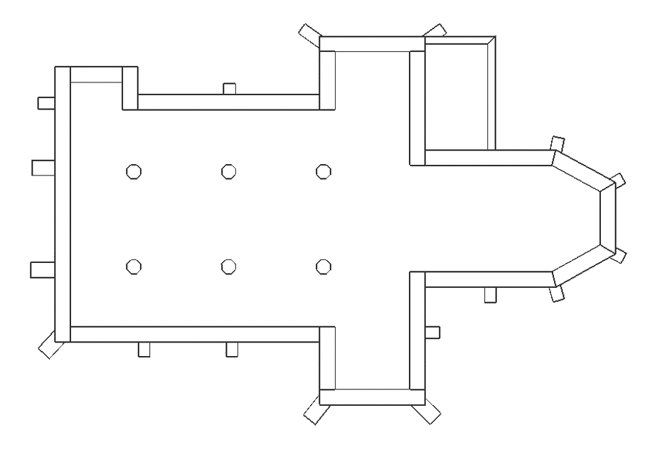
Tip: Switch of Entity Snaps and turn OrthoMode on while tracing the walls. This will give a more perfect final result. You should now have something that looks like this:
Note the differing width of some of the walls.
Adding columns and buttresses
After I finished tracing the walls, I added the columns and buttresses.
How to Do This
- For the columns:
- Use Polygon to make an octagonal shape.
- Extrude the shape. (Again, the height does not matter for now).
- To make the other columns: repeat step 1 and use a ArrayRec (3×2).
- For the buttresses: use Polysolid and Connect to Nearest to connect the buttresses to the walls.
You should now have something that looks like this: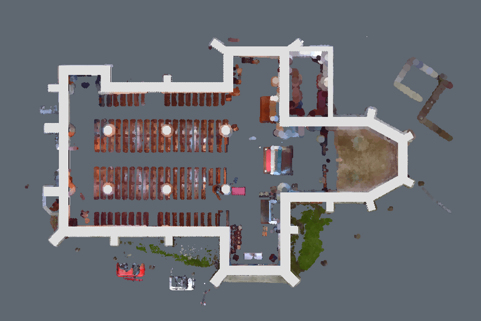
Making the roofs
To make the roofs I drew polysolids and using the Manipulator, I rotated them to match the point cloud.
How to Do This:
- Unclip the section boxes and view the whole model.
- Hide the point cloud.
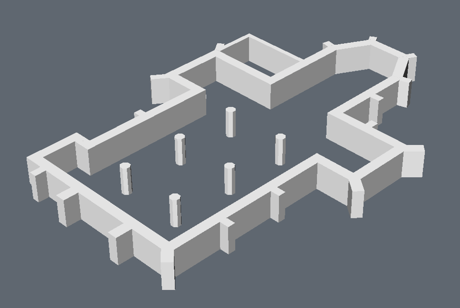
- Draw Planar Solids (width of 0,5m) on top of the walls(these will become the roofs when they are tilted.) It should look something like this (when the walls are hidden):
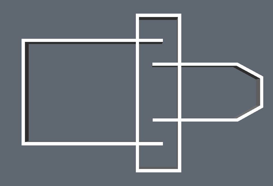
- Tilt the correct roofs inwards by 45°: long click on a solid and use the Manipulator.
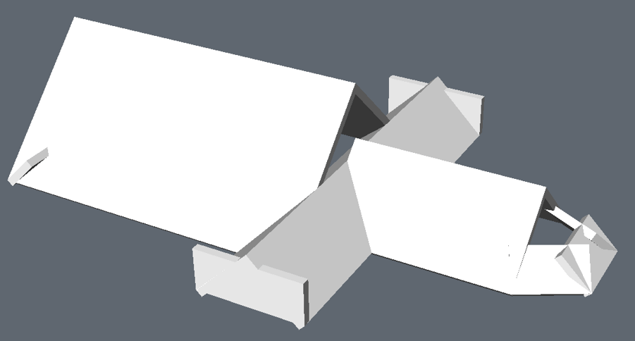
- L-connect the roof.
- Use DmPushPull to improve the appearance.
- Continue creating roof sections. Use the 3D point cloud as a reference.
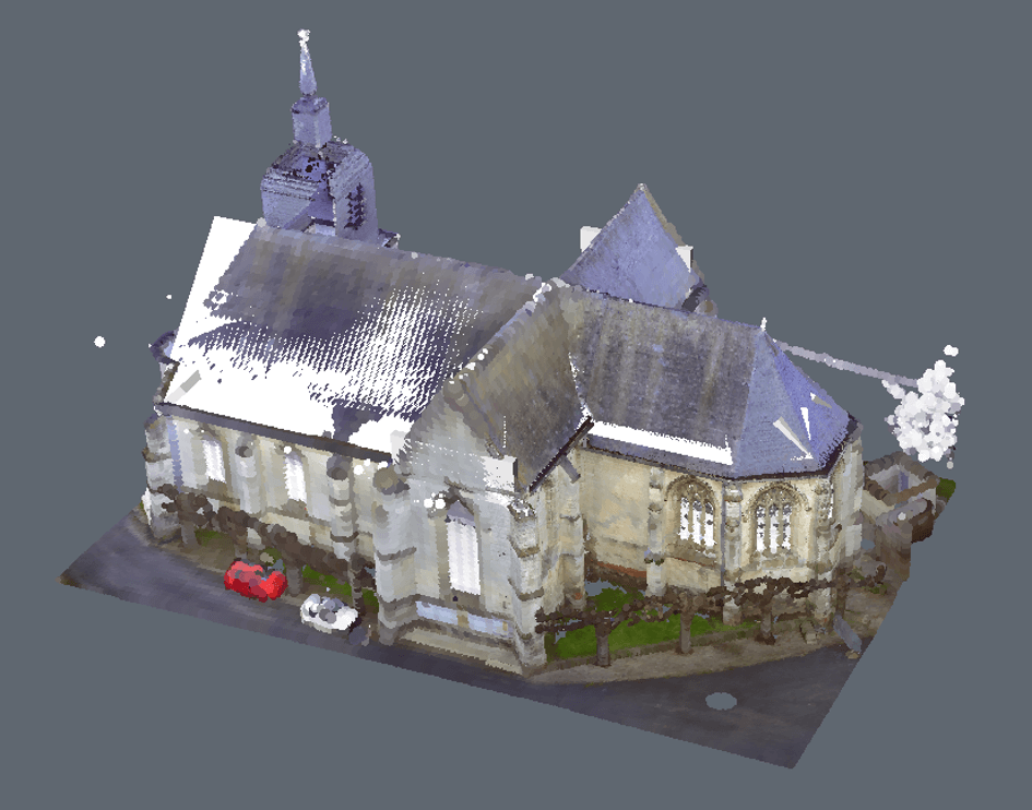
- Use the manipulator to tilt the roofs to better match the join.
- Use L-connect and Slice to clean up the connections, so that no overlap exists.
- Repeat these actions until you are happy with the roof. You should now have something that looks like this:
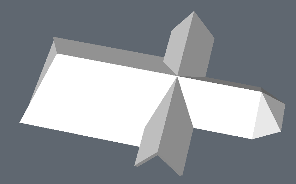
Connecting walls to roofs
I used PushPull to change the height of the walls until they reach the roofs. Then I subtract the walls from the roof to get a clean connection. You could also use L-Connect for this, but with complex roofs, this does not always produce the desired results.
How to Do This:
- Show everything, except for the point cloud.

- Select the top face of a wall.
- Use SelectAlignedFaces to select the top faces of the walls.
- DmPushPull the walls to the highest starting point of the roofs.
 You should now have something that looks like this:
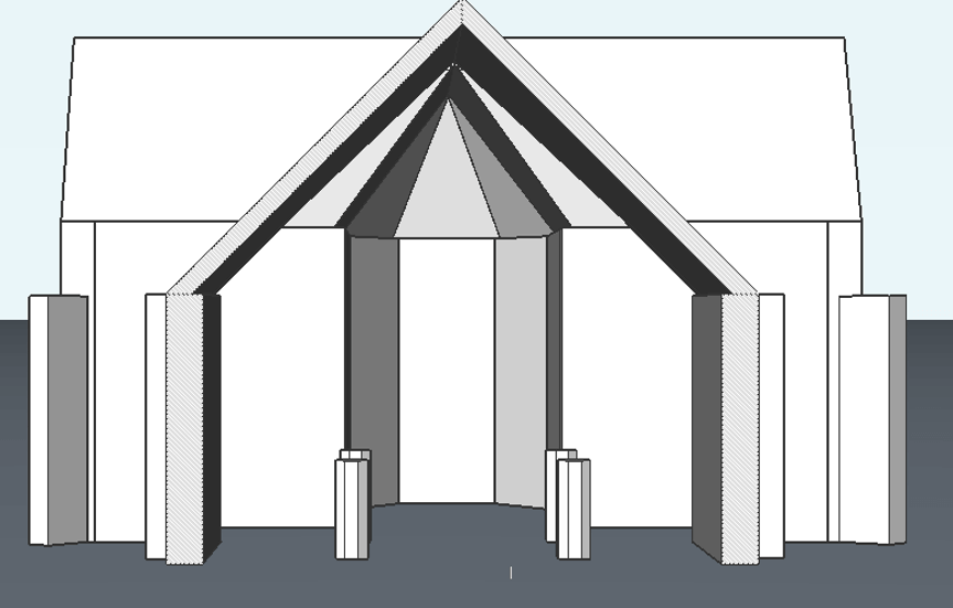
- To clean up the outer ends of the cross, Slice away excess geometry.
- Use Connect to Nearest to match the ending of the walls to the roofs.
- Finish with DmPushPull and Subtract. You should now have something that looks like this:
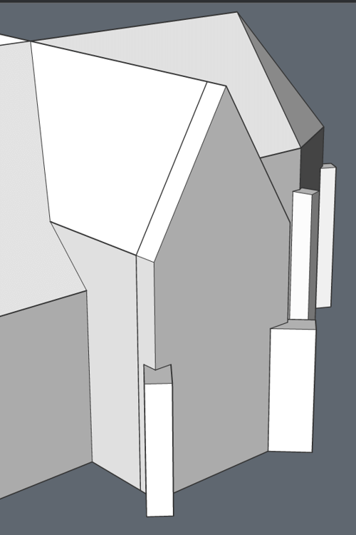
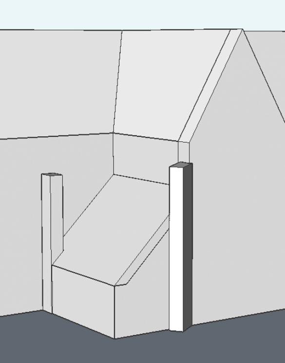
- Clean up the extra room attached to the church. Give it a sloped roof. (Use Polysolid, the Manipulator, Subtract and Connect to Nearest). You should now have something that looks like this:
That's all for now. In the next post in this Point Cloud to BIM series, I will show you how I created the windows and details.
Download BricsCAD free for 30-days
Start using Point Clouds in BricsCAD Today
Permanent or subscription licenses that work in all languages, in all regions.
Point Cloud to BIM Model:
- The Outside
- Windows and Towers
- The Interior



 You should now have something that looks like this:

