In this post, you will learn how to use and customize pattern hatches in BricsCAD®. BricsCAD provides you with two ways to create custom hatch patterns: (a) simple patterns defined with the Hatch and -Hatch commands; and (b) edit the default.pat file or write new .pat files with a text editor. We look at both methods in this post.
Despite seemingly complex, hatch patterns consist of the same three basic elements as linetypes: dashes, gaps, and dots. The pattern repeats itself, which is done by specifying an offset distance and an angle, as illustrated below:

QUICK SUMMARY OF PATTERN DEFINITIONS
Hatch patterns are stored in .pat files and are applied with the Hatch command. Each hatch pattern definition consists of at least two lines of text, a header that labels the pattern, followed by one or more lines of data that describe the pattern. (Gradients are hardcoded and cannot be customized.)
LINE 1: HEADER
Example: *Name,Description
* (asterisk) --- indicates the start of the hatch pattern
Name --- names the pattern
, (comma) --- separates the name from the description
Description --- describes the pattern
LINE 2: HATCH PATTERN DATA
Example: 45, 0,0, 0,0.125
45 --- specifies the angle of the line segment
0,0 --- specifies x,y coordinates of the start of the line segment.
0,.125 --- specifies ending coordinates of the line segment. dash definition --- defines dashes in the line segment using the same code is in linetypes:
- Positive number: draws a dash, such as 0.25
- Zero (0): draws a dot
- Negative number: draws a gap, such as -0.25.
NOTE To include comments in the .pat file, prefix lines with a semi-colon ( ; ).
The result is like the samples illustrated below.

Examples of hatching patterns provided with BricsCAD
BricsCAD cannot create hatch patterns made of circles and other nonlinear objects, but BricsCAD can solid-fill and gradient-fill areas in any color.
BricsCAD comes with 87 hatch patterns, plus solid fill and nine, gradient fill patterns. Even so, your office drafting standard may well require additional patterns. In this post, we'll look at how to create hatch patterns and edit existing ones.
Where Do Hatch Patterns Come From?
The -Hatch command creates hatch patterns at the command line; Hatch displays a dialog box to do the same thing. Unlike linetypes, the pattern file is loaded automatically the first time you use the Hatch or -Hatch commands (formerly the BHatch command). Hatch patterns are defined in files external to BricsCAD:
- default.pat contains the hatch patterns you use most commonly
- pat contains hatch patterns as defined by the ISO
- Other .pat files can also contain hatch patterns, but it is easier to keep all patterns in a single file
These are the folders in which BricsCAD stores its pattern files (replace <login> with your login name):
| Windows: | C:\Users<login>\AppData\Roaming\Bricsys\ BricsCAD\V20\en_US\support |
|---|---|
| Linux: | /home/<login>/Bricsys/BricsCAD/V20/en_US/Support |
| macOS: | /Users/<login>/Library/Preferences/Bricsys/BricsCAD/V20x64/en_US/Suppor |
HOW HATCH PATTERNS WORK
When you apply hatching to an area, BricsCAD generates a repeating pattern of parallel lines and gaps based on the definition in the .pat file. The pattern comes to a stop when it reaches a boundary; if BricsCAD cannot detect a boundary, it refuses to place the pattern.
Once the hatch is in place, you can use the Move command to move the hatch pattern elsewhere in the drawing, if you so chose.
BricsCAD can create non-associative and associative hatch patterns; the Associative toggle is found in the Options area of the Hatch and Gradient dialog box.
- Non-associative means the area of the pattern is fixed. When you change the boundary, the pattern remains in place, as illustrated below. This property is useful when you want the pattern to remain fixed.
- Associative hatching means the pattern's shape updates as you change the boundary.

How associative hatching works
In either case, you can move the pattern independent of its boundary. This is because BricsCAD treats both kinds of hatches as blocks. You can use the Explode command to explode blocks into their constituent lines.
You can use the HatchEdit command or the Properties command to edit parameters of hatch, solid, and gradient patterns.
System Variables that Control Hatches
BricsCAD has system variables that control how hatches are created and report their most recent settings. In the Settings dialog box (Settings command), enter "hatches" in the search field:

Settings that affect hatches
Creating Custom Hatch Patterns
BricsCAD provides you with two ways to create custom hatch patterns: (a) simple patterns defined with the Hatch and -Hatch commands; and (b) edit the default.pat file or write new .pat files with a text editor. We look at both methods in this post. Unlike linetypes, you cannot create hatch patterns in Drawing Explorer.
When you create simple hatch patterns with the Hatch command, BricsCAD does not, save this (unlike custom linetypes created with Linetype.) For this reason, think of the first method of creating custom hatch patterns "on-the-fly".
Creating a Hatch "on-the-fly"
Your options for "creating a hatch "on-the-fly" are limited to simple patterns. Using the -Hatch command, you access the Properties option, followed by User defined, as follows:
Enter the -Hatch command (formerly the Hatch command, with no hyphen prefix):
: --hatch
Current hatch pattern: ANSI31Select the P (properties) option, and then the U (user defined) option:
Specify internal point or
[hatch Properties/Select entities/Remove boundaries/Advanced options/Draw order/Origin/ANnotative/Layer/Transparency/Undo]: pEnter a pattern name or
[? to list patterns/Solid fill/User defined/Gradient]<ANSI31>: uSpecify three parameters for custom hatch patterns: Angle, Spacing, and Crosshatching. First, the angle:
Set Angle for lines or
[Proceed]<0>: 45Second, the spacing between parallel lines.
Space between standard pattern lines <1>: 2
Third, decide if you want the pattern crosshatched. That means the pattern is repeated at 90 degrees to the first one.
Cross-hatch area?
[Yes-cross hatch/No-one direction]<No>: yFinally, you select the object or boundary to hatch:
Specify internal point or
[hatch Properties/Select entities/Remove boundaries/Advanced options/Draw order/Origin/ANnotative/Layer/Transparency/Undo]: (Pick a point in the drawing to apply the pattern.)

Defining a custom hatch pattern inside BricsCAD
BricsCAD draws the pattern, but --- as mentioned earlier --- the custom hatch is not saved to a .pat file.
HATCH COMMAND
Creating custom hatch patterns with the Hatch command is more like filling out a form:
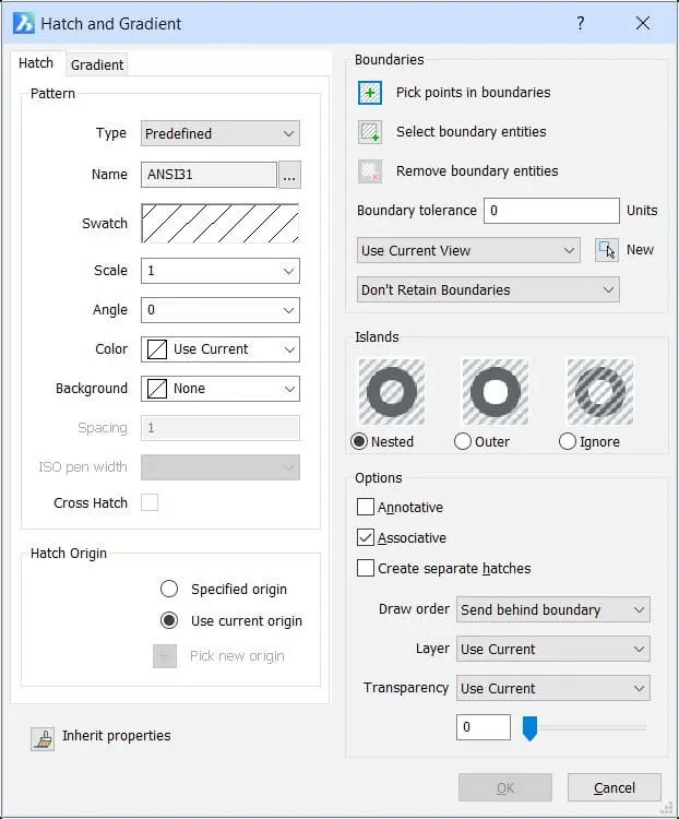
From the Draw menu, select Hatch. (Alternatively, type Hatch at the command prompt). Notice the Hatch and Gradient dialog box.

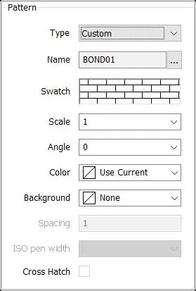
From the Type drop list, select Custom.

BricsCAD allows you to enter values for Angle, Spacing, and Cross Hatch, as well as the color of the cross-hatching and the background color. Enter values such as these:
Angle 45
Spacing 2
Cross Hatch YesClick the + Pick points in boundaries button and then select the area you want hatched.
Press Enter to return to the dialog box and then click OK. BricsCAD applies the custom pattern.
Understanding the .pat Format
Let's dig into the contents of the default.pat file to get a better understanding of how a pattern is constructed.
- Start a text editor (not a word processor), such as Notepad on Windows, Text Edit on Linux, or TextEdit on Mac.
- In Windows, open the default.pat file from the \Users<login>\AppData\Roaming\Bricsys\BricsCAD\V14x64\ en_US\support folder.
In Linux, open the default.pat file from the /home/login/Bricsys/BricsCAD/V20/en_US/Support folder.
In MacOS, open the default.pat file from the /Users/login/Library/Preferences/Bricsys/BricsCAD/V20x64/ en_US/Support/default.lin folder. - Scroll down a bit and take a look at the seemingly-incomprehensible series of numbers and punctuation contained by this file. I've reproduced the first dozen lines here:
; Note: Dummy pattern description used for 'Solid fill'.*SOLID, Solid fill
45,0,0,0,0.1*ANSI31,ANSI Iron
45, 0,0, 0,0.125*ANSI32,ANSI Steel
45, 0,0, 0,0.375 45, .176776695,0, 0,.375
COMMENT AND HEADER LINES
The definition of a hatch pattern consists of two or more lines of text. The first line is called the header, such as *SOLID, Solid fill.
Comment
The semicolon ( ; ) indicates a comment line, such as
; Note: Dummy pattern description used for 'Solid fill'.
That lets you include notes to yourself that are ignored by BricsCAD.
Start of Definition
The asterisk ( * ) is important because it signals to BricsCAD the start of a new hatch pattern definition.
Pattern Name
Following the asterisk comes the name for the hatch pattern, such as SOLID. The name must be unique in the file. If it isn't, BricsCAD uses the first pattern it finds by that name.
The comma following the name merely separates the name from the description. The comma is optional; it doesn't have to be there (a space works just as well).
Description
The text following the pattern name is the description displayed by the -Hatch ? command, such as "Solid fill." This description is also optional but highly recommended. You are limited to a maximum of 80 characters for the name, comma, and the description. If you need more room for the description, use comment lines, such as:
; Note: Dummy pattern description used for 'Solid fill'.
*SOLID, Solid fill
THE HATCH DATA
With the comment lines and the header line out of the way, let's get down to the nitty-gritty hatch pattern data and how it is coded. Lines 2 and following are the data, such as:
0, 0,0, 0,.275, .2,-.075 90, 0,0, 0,.275, .2,-.075
Every line of data uses the same format:
angle, xOrigin, yOrigin, xOffset, yOffset [, dash1, ...]
Angle
The angle is the angle at which this line of hatch pattern data is displayed. The "0" means the hatch line is drawn horizontally; a "90" means the line is drawn vertically, and so on. A comma ( , ) separates the numbers.
xOrigin and yOrigin
The xOrigin specifies that the first line of the hatch pattern passes through this x-coordinate. The value of the yOrigin means that the first line of the hatch pattern passes through this y-coordinate.
xOffset and yOffset
The xOffset specifies the distance between line segments, aka the gap distance. You use this parameter only to specify the offset for vertical or diagonal lines (To specify the distance between dashes, use the dash1 parameter.) In most hatch patterns, xOffset has a value of 0.0. Even though this parameter is rarely used, it is not optional.
The yOffset is the vertical distance between repeating lines, and is used by every hatch pattern.
Dash1,...
dash1 defines the dashes in the hatch pattern line (the code is the same as for linetypes):
- A positive number, such as 0.25, is the length of the dash.
- A 0 draws a dot.
- A negative number, such as -0.25, draws a gap.
TIP The dot drawn by the hatch pattern may create a problem when it comes time to plot. If you find that the dots in a hatch pattern are not printed, use a very short line segment, such as 0.01, instead of a 0.
When you are finished editing a pattern, save the .pat file.
ADDING SAMPLES TO THE HATCH PALETTE
BricsCAD adds visual samples of your custom hatch patterns to the palette automatically. You can have more than one .pat file; however, the additional ones are limited to one pattern definition per file, and the definition's name must match the file name.
TIPS ON CREATING PATTERN CODES
Some miscellaneous comments on hatch pattern coding:
Tip 1: Hatch pattern lines are drawn infinitely long. What this means is that BricsCAD draws the line as long as necessary, as long as it reaches a boundary. BricsCAD will not draw the hatch pattern unless it does find a boundary.
Tip 2: At the very least, each line of pattern code must include the angle, x- and y-origin, and the x- and y-offset. This draws a continuous line.
Tip 3: The dash1 parameter(s) is optional but when used draws a line with the dash-gap-dot pattern.
Tip 4: It's a lot easier for someone else (or you, six months from now) to read your hatch pattern code if you use tabs and spaces to format the code into nice columns.
Tip 5: To change the angle of a hatch pattern upon placing it in the drawing, you've got a couple of options:
Specify the angle during the Hatch command.
Set the angle in system variable SnapAng. The effect of SnapAng on the hatch pattern angle is additive: if the hatch pattern defines the lines drawn at 45 degrees and SnapAng is 20 degrees, then BricsCAD draws the hatch lines at 65 degrees. For example:
: snapang
New current angle for SNAPANG <0>: 20
The x-offset and y-offset parameters are unaffected by the angle parameter because x-offset is always in the direction of the line and y-offset is always perpendicular (90 degrees) to the line.
If you are uncomfortable using system variables, then the Snap command provides the same opportunity via the Rotate option:
: snap
Snap is off (x and y = 0.5000): ON/Rotate/Style/Aspect/<Snap spacing>: r
Base point for snap grid <0.0000,0.0000>: 1,1
Rotation angle <0>: 45
Tip 6: You can specify a weight (or line width) for hatch patterns line. If you wish, you can also make thick-looking patterns by using closely spaced lines, like this:
Thick_Line, Closely spaced lines
0, 0,0, 0,.25 0, 0,.01, 0,.25 0, 0,.02, 0,.25
Tip 7: To draw dash and gap segments at an angle, use the sine of the angle in degrees, like this:
| Angle | Dash length (sine) |
|---|---|
| 0 | 0 |
| 30 | 0.433 |
| 45 | 0.707 |
| 60 | 0.866 |
| 90 | 1.0 |
Tip 8: You cannot specify arcs, circles, and other round elements in a hatch pattern file. Everything consists of straight lines and dots. To simulate circular elements, use a series of very short dashes.
- Introduction
- 55 Tips for BricsCAD Users
- Settings
- Changing the Environment
- Custom User Interface
- Introduction to the Customize Dialog Box
- Customize the Menu Bar & Context Menus
- Customize Toolbars and Button Icons
- Writing Macros and Diesel Code
- Ribbon Tabs and Panels
- Keystroke Shortcuts, Aliases, & Shell Commands
- Customize Mouse, Double-click & Tablet Buttons
- Absolutely Everything You Need to Know About The Quad
- Rollover Properties
- Workspaces and the User Interface
- Designing Tool & Structure Panels
- Creating Simple & Complex Linetypes
- Patterning Hatches
- Decoding Shapes & Fonts
- Coding with Field Text
- Writing Scripts
- Programming with LISP (Introduction)
- LISP Functions
Explore BricsCAD
Download BricsCAD Free Trial | Sign Up For News & Updates | Shop Online For BricsCAD Desktop Software


