Parametric modeling is a great way of streamlining your CAD work. However, it's easy to feel daunted by tables, formulas, constraints and parameters. With that in mind, I've come up with a practical, exercise, that anyone with a basic knowledge of CAD can follow. It will give you an idea of the basics of 3D parametric modeling in BricsCAD.
In this exercise, you will learn how to use parametric modeling to make a set of drums for a drumkit. You will do this by modeling one drum and adding parameters and constraints. All you need to do is change the values of these parameters to create the other drum sizes. You will finish by adding a design table.
If you get stuck don't worry, you can download the complete model in the project file.

Make a Drum Kit With Parametric Modeling
Time to complete: 1-2 Hours
Difficulty: 8/10
Download the project .dwg files here
Before we begin..
If you need to manually enter a value during the exercise, it will be shown in green.
Quick guide to terminology:
- Parameter -- defines the position, distance, and angle of geometry
- Constraint -- rules: position, slope, tangency, dimension, and relationship of geometry
- Expression -- formula or absolute value of a parameter or constraint
How to model a drum kit with parametric modeling
Start by modeling the basic parts of the drum:
- Shell
- Skin
- Ring
- Bolt
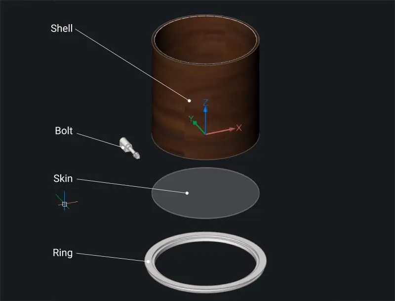
You can model them yourself or download the project file.
Note: It's a good idea to use 0,0,0 as the origin point for the center of the drum. This helps when adding constraints later.
Now it's time to create components, if you don't want to you can use the model in the project download file and skip to Step 17.
Add 3 new parameters:- Open the Mechanical Browser
- Right-click and select Add new parameter from the drop-down menu.
- Repeat Step 2, 2 times.
- Click on the new parameters and change the Expression (their values) -- use the bottom half of the Mechanical Browser:
- Name = height
Expression = 300 - Name = rad
Expression = 150 - Name = bolts
Expression = 6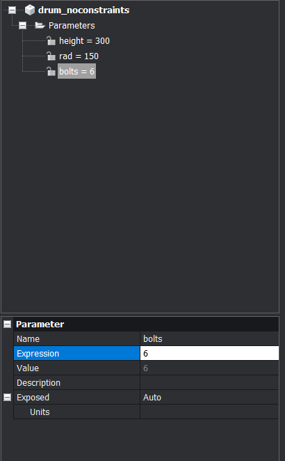
- Name = height
Now add a Coincidence constraint to the bottom face of the drumkit to "lock" it in position.

- The Command line will display: Select a pair of subentities or
[Autoconstrain/WOrld/BLock/selection options (?)]<Autoconstrain>: Choose the WOrld option - The Command line displays: Select reference coordinate system subentity
[Origin/X axis/Y axis/Z axis/XY plane/YZ plane/ZX plane]: Choose the Origin option - Select the bottom face of the drum shell.
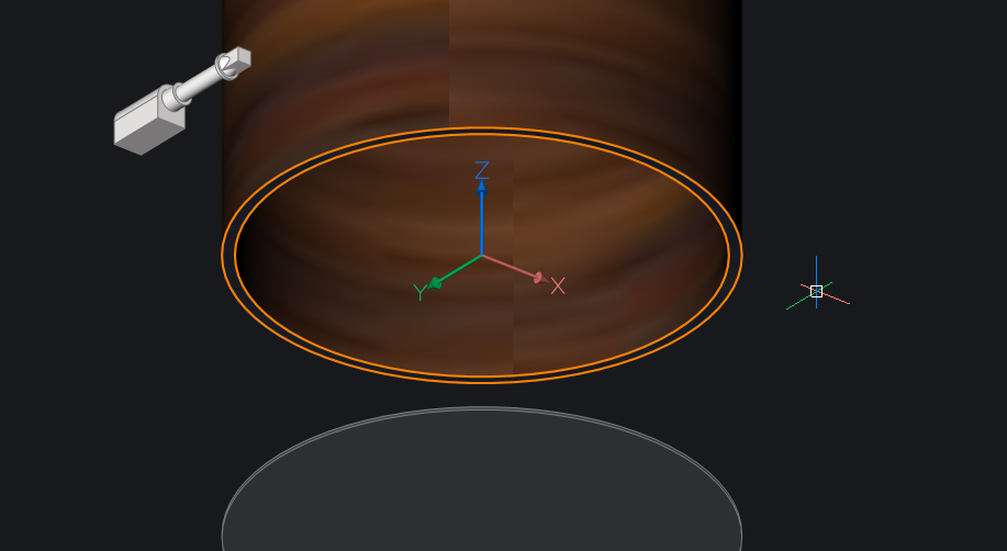
The face of the drum shell is now fixed in position.
TIP It's best-practice to set coincidence constraints first.
You could also use a Fix constraint for this step. However, it will give you less options later.
- The Command line will display: Select a pair of subentities or
Now convert the skin, rim and bolts into components. Begin by setting the constraints, then convert each item into a component.
Set a Radius Constraint to the outer face of the drumskin.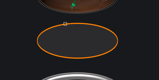
Change the value of Expression to 'rad'.
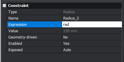
The drumskin radius is now the same value as the 'rad' parameter. If you change the value of 'rad' the radius of the drumskin will change to match.
Test this: right-click on the 'rad' parameter and select Animate.
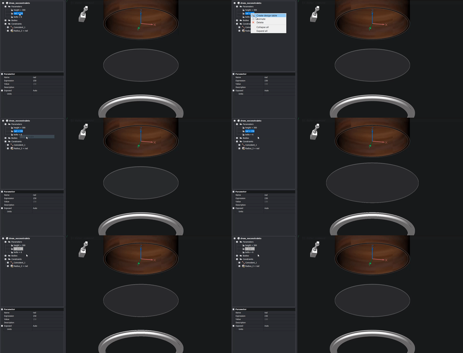
Use BMForm to convert the skin into a component.
Select the 'External component' option and set the origin point as the center of the top face. Give it a sensible name and storage location.
Once you have created the component it will appear in the Mechanical Browser.
Right-click the 'rad' constraint and select Link to Parameter.
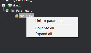
Test the constraints now. Right-click on the 'rad' parameter and select Animate.
Repeat steps 4-9 to add Radius Constraints to the ring and change the values (see illustration below). Set the origin point to the center of the ring.
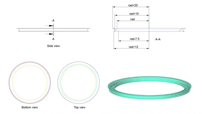
Click to enlarge
Mirror/Copy the bolt.
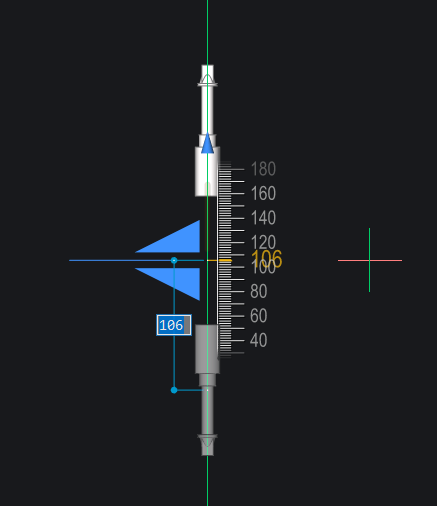
Add a Distance Constraint between the two faces (see illustration).
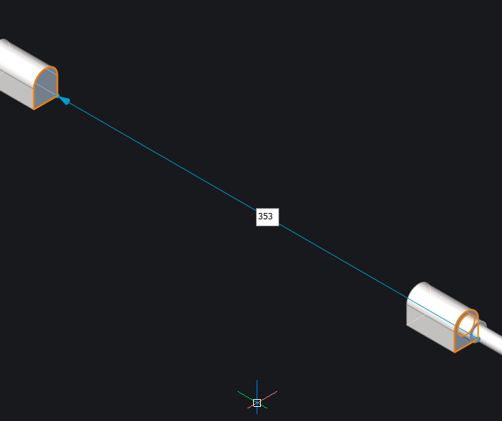 Note: The first face you select will be the "stationary" face. The second face will move relative to the location of the first face.
Set the Distance to 'height-112'.
Test it: right-click the 'height' parameter and select Animate.
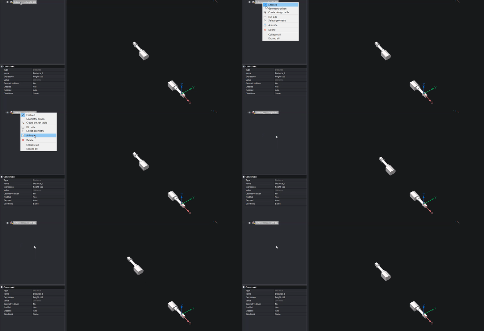
Use BMForm to convert the bolts into a component. Again, use the External option.
Set the origin point to the center of the washer on the bolt. This should be the bolt that does not move when the height parameter is animated.
The face should be the face that will touch the bottom face of the ring (see image).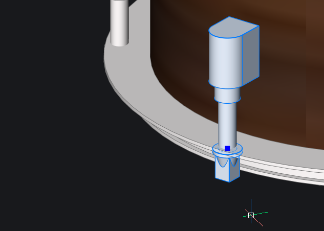
The blue dot indicates the origin point. This is the "stationary" point.
Right-click the 'height' constraint select Link to parameter.
Mirror/Copy the skin and the ring.
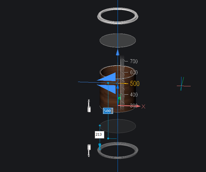
Add a Coincidence Constraint to fix the bottom drum skin in place.
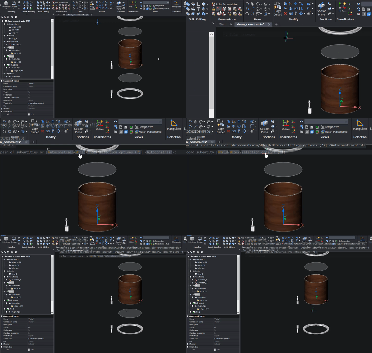
- The Command line will display: Select a pair of subentities or
[Autoconstrain/WOrld/BLock/selection options (?)] <Autoconstrain>: Choose the WOrld option - The Command line displays: Select reference coordinate system subentity
[Origin/X axis/Y axis/Z axis/XY plane/YZ plane/ZX plane]: Choose the Origin option - Select the top face of the bottom skin.
If you complete this step correctly, the skin should jump to the bottom of the shell. However, the skin is fixed in position relative to the world coordinate system and not the shell.
Fixing components relative to the world coordinate system makes their behavior more predictable and prevents them from "jumping around".
- The Command line will display: Select a pair of subentities or
Create a Coincidence constraint between the inner of the bottom ring and the bottom face of the drum skin.
Note: If you prefer you could set this constraint and the following distance constraints, from the world coordinate system. I have not, in case I wish to change the thickness of the drum skin at a later point in time.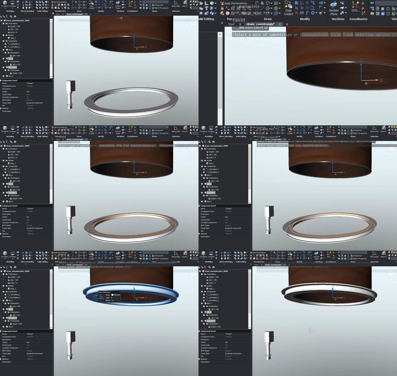 If you complete this step correctly, the ring should jump to the bottom of the skin.
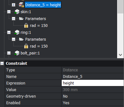
Add a Distance constraint between the top and bottom faces of the shell.
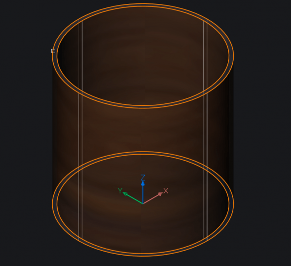
Set the Distance to 'height'.
Add a Distance constraint between the top face of the bottom skin and the bottom face of the top skin.
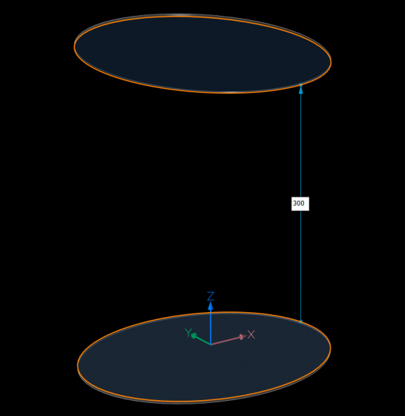
Perspective added for clarity.
Set the Distance to 'height'.
Add a Distance constraint between the top face of the bottom ring and the bottom face of the top ring.
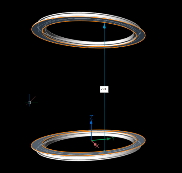
Perspective added for clarity.
Set the expression to 'height -6'.
So far so good! Check and see how everything is looking:Right-click the 'height' parameter and select Animate.
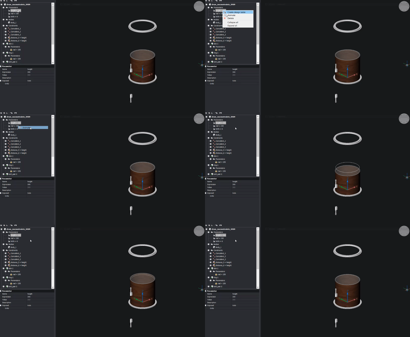
If you animate the 'rad' parameter, you'll see that the shell doesn't move with the rest of the model, so let's fix that!
Add two Radius Constraints to the inner and outer faces of the shell. Set the outer radius Expression to 'rad' and the inner radius Expression to 'rad-7.5'.
Now all that's left is to add the bolts!
Move the bolts into position with the bottom ring.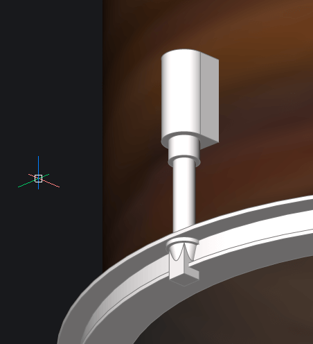
At this point, you'll notice that there is a problem: the ring isn't large enough. Luckily this is easy to fix!
In the Mechanical Browser, right-click on the ring and select Open from the drop-down menu.
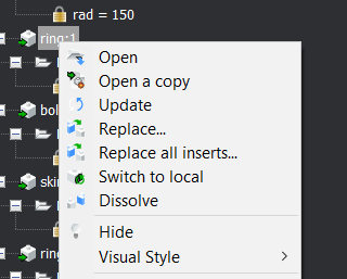
The component will open in a separate drawing. Change the expression of the largest radius from 'rad+20' to 'rad+30'.
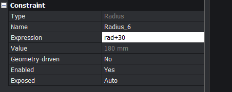
Save the drawing.
Open the main drawing back up (click the tabs).
In the Mechanical Browser, right-click on the ring and select Update from the drop-down menu.
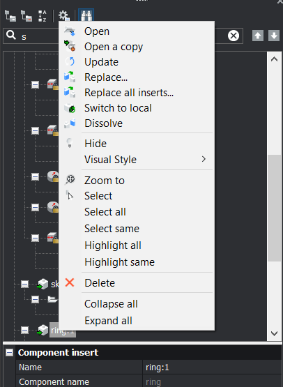
Note: both rings automatically update.
Enter ArrayPolar. Select the bolt component as the entities to array and use 0,0,0 as the origin point.
In the Mechanical Browser, change the parameters of the array to:
- Radius = 'rad+15'
- Items = 'bolts'
- Angle between items = '360/bolts'
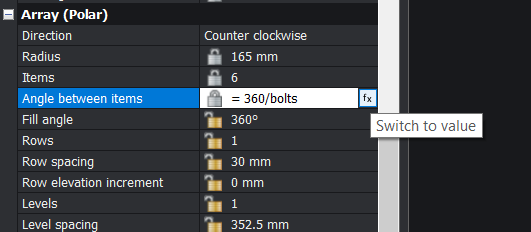
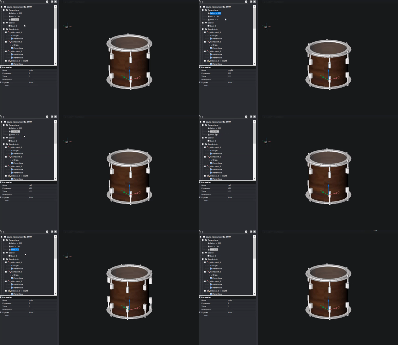
In the Mechanical Browser, animate the various parameters or manually type a new value for each parameter. You now have a way to quickly create drums of different sizes!
Finishing up
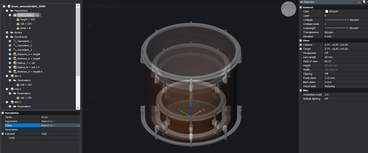
Typically, drums come in just a few standard sizes. This is where Design tables can be useful!
I created this design sheet for my drum kit, all I needed was a simple spreadsheet software package. I then saved the table to .csv. Make sure the column headers match the parameter names.

An example of a design table created in a spreadsheet software package.
To load a design table into BricsCAD is really easy:
Enter DesignTable.
- The Command line will display: Create design table
[From file/Empty] <From file>: Choose the From file option - Select the .csv file.
The Mechanical Browser will then display a new branch with a grid icon (just below the Parameters branch).
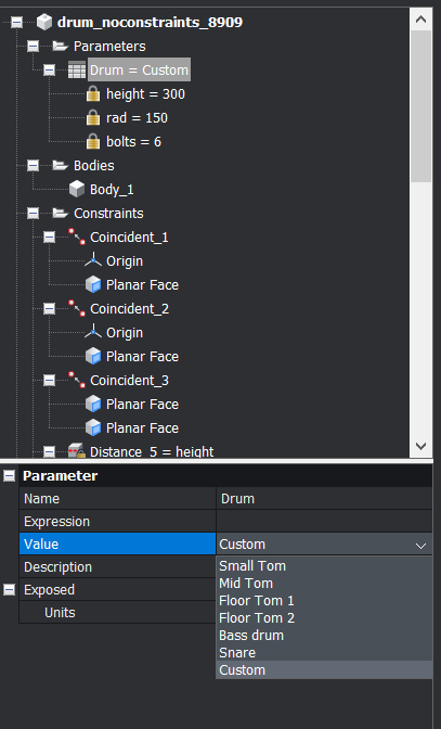
- The Command line will display: Create design table
Navigate to the bottom of the panel. Next to the word Value there will now be a drop-down menu. This will provide you with all the size options available in the design table.

And that's it! Your first parametric model. Just add some hardware and a few cymbals and you're rocking!

Automatic parameters and constraints
BricsCAD includes a Parameterize command. This automatically adds parameters and constraints to a drawing. However, for the purposes of this exercise, you manually added parameters and constraints to a drawing. Feel free to test out Parameterize for yourself to see how it works!
Learn more
If this has wet your appetite for parametric modeling, why not check out our BricsCAD BIM -- Grasshopper connection!



 Note: The first face you select will be the "stationary" face. The second face will move relative to the location of the first face.


 If you complete this step correctly, the ring should jump to the bottom of the skin.


