In this post, we look at how to design custom, BricsCAD® dialog boxes with DCL (Dialog Control Language). DCL allows programmers to create custom dialog boxes for LISP routines. DCL was added to BricsCAD in V8 for compatibility with AutoCAD®.
DCL is a structured language used to describe the elements (called "tiles") that make up dialog boxes. Tiles includes edit boxes, list boxes, radio buttons, image tiles, and title bars. Each of these has one or more attributes, such as its position, background color, and the action it performs.
A QUICK HISTORY OF DCL
Autodesk® first added DCL as an undocumented feature to AutoCAD® Release 11 for Windows. It was designed to for creating platform-independent dialog boxes. At that time, Autodesk® produced versions of AutoCAD® for "every viable engineering platform," which included DOS, Windows, Unix, Macintosh, and OS/2, and DCL was part of a project code-named "Proteus," whose aim was to make AutoCAD® work and look identical on every operating system.
As the figures below show, the project was a success. First, here is AutoCAD® Release 11's Drawing Aids dialog box running on DOS:

And here is the same dialog box in the Windows version of AutoCAD® Release 11:

Notice how similar the DOS and Windows dialog boxes look. (The Drawing Aids dialog box is now known as the Options dialog box.)
By Release 14, however, Proteus became meaningless, because Autodesk® chose to support only the Windows operating system. But DCL continues to hang around as the only way to create dialog boxes with LISP, and Bricsys makes good use of DCL for its support of Linux, macOS, and Windows.
Applications written in LISP, SDS, and DRx can make use of DCL for dialog boxes. Menu and toolbar macros can too, when they link to LISP routines that call the DCL code. (VBA does not use DCL, because it has its own dialog construction environment.)
Bricsys provides no programming environment to help you create DCL files --- it's hand coding all
the way. That means a text editor such as NotePad in Windows and Text Edit in Linux or Mac will
be your DCL programming environment. Some third-party developers have created DCL development tools.
When you want a LISP routine to display a dialog box, you need to write two pieces of code:
- Code in a .dcl file that defines the dialog box and the functions of its tiles.
- Code in the .lsp file that loads the .dcl file and then activates the tiles.
Working with dialog boxes always involves a pair of files, .dcl and .lsp, with the LISP code controlling the dialog box code.
A drawback to DCL is that it cannot create self-modifying dialog boxes, such as ones that add or remove buttons. It can, however, dynamically change the contents of droplists and such.
Elements of a dialog box
What Dialog Boxes Are Made Of
Dialog boxes can consist of many elements, such as radio buttons, sliders, images, tabs, and check boxes. These elements are called "tiles." DCL allows you to create many different types of elements, but it does not have tiles for every element found in today's dialog boxes. That's because DCL hasn't been upgraded since it was introduced some 20 years ago. (Those elements not possible with DCL can be created through VBA.)
The figure below illustrates many of the dialog box elements that are possible with DCL, along with some names of specific DCL tiles.
Most tiles are visible, but some are invisible, such as the row and column tiles highlighted in the figure above with a blue rectangle:
HOW DCL OPERATES
The two pieces of code that are required to make dialog boxes operate are:
- DCL code that specifies the layout of tiles and their attributes in the dialog box.
- LISP code that activates and controls the dialog box.
You do not need to specify the overall size of the dialog box; BricsCAD takes care of that by automatically sizing it. The default is that tiles are stacked in columns; you only need to specify when tiles should be aligned in a row.
Some back and forth is permitted while running DCL and LISP; this is known as "callbacks." Callbacks are used to provide names to file dialog boxes, to gray out certain buttons, to change the content of popup lists (droplists), and so on.
This post shows you how to write DCL with LISP code. A later post will provide you with a comprehensive reference to all DCL tiles, their attributes and related LISP functions.
Your First DCL File
Before writing any code for a dialog box, it is helpful to plan out the tiles. Where will the buttons, droplists, and text entry boxes go in the dialog box? It's a good idea to get your pencil and then sketch your ideas on paper.
For this tutorial, you will create a dialog box that displays the values stored in these system variables:
LastPoint --- stores the coordinates for the last point entered in the drawing.
LastAngle --- stores the angle defined by the last two points entered.
LastPrompt --- stores the last text entered at the command line.
Take a moment to think about the design of the dialog box. It would have a title that explains the purpose of the dialog box. It probably should have three lines of text that report the name and value of each system variable, and it should have an OK button to exit the dialog box.
It might look like this:

DCL PROGRAMMING STRUCTURE
The programming structure of this dialog box looks like this:
Start the dialog box definition:
- Specify the dialog box's title
- Specify a column:
System variable LastPoint and its 3D coordinates
System variable LastAngle and its angle
System variable LastPrompt and its text
- Locate the OK button
End the dialog box definition.
In this first tutorial, you will write just enough code to display the dialog box and its OK button. In the tutorials that come later, you add the bells and whistles.
Start Dialog Box Definition
The content of every .*dcl *file begins with a name attribute. This is the name by which the dialog code is called later by the associated LISP routine. The name function looks like this:
name: dialog {
Like LISP, an open brace needs a closing brace to signal the end of a dialog box definition:
}
Between the two braces, you write all the code that defines the look of the dialog box.
For this tutorial, name the dialog box "lastInput," as follows:
lastInput: dialog { }
DCL names are case-sensitive, so "lastInput" is not the same as "LastINPUT" or "lastinput."
Dialog Box Title
The text for the dialog box's title bar is specified by the label property, as follows:
name: dialog {
label = "Dialog box title";
}
Label this dialog box "Last Input" like this:
lastInput: dialog {
label = "Last Input";
}=
The title text needs to be surrounded by quotation marks ( " ). The label property must be terminated with a semicolon ( ; ). And it's helpful to indent the code to make it readable.
OK Button
Every dialog box needs an exit button, or at least an "OK". (Windows places a default X button in the upper-right corner of every dialog box, which also works to exit dialog boxes made with DCL!)
Buttons are defined with the button property, followed by the properties of the button enclosed in braces:
: button { }
Because dialog boxes can have multiple buttons, every button must be identified by a property called the "key." The key is how LISP gives instructions to buttons. Use the key attribute to identify this OK button as "okButton," as follows:
key = "okButton";
The button needs to display a label for users to read. This is an OK button, so label it " OK " with the label attribute, as follows:
label = " OK ";
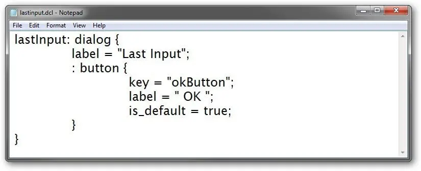
Let's put all of these together. The code added for the OK button is shown here in color, with the key, label, and is_default attributes. (See below for info about the default attribute.) We have a button identified as "okButton," sporting the label "OK," and is set at the default tile.
lastInput: dialog {
label = "Last Input";
: button {
key = "okButton";
label = " OK ";
is_default = true;
}
}
TIP The DCL code for the OK button is like a subroutine. The same code can be reused any time a dialog box needs an OK button, which is pretty much all the time. Later, you will see how to create subroutines with DCL code.
QUICK SUMMARY OF DCL METACHARACTERS
| DCL | Metacharacter | Meaning |
|---|---|---|
| // | (slash-slash) | Indicates a comment line |
/* |
(slash-asterisk) | Starts comment section |
*/ |
(asterisk-slash | Ends comment section |
| : | (colon) | Starts a tile definition. Predefined tiles, like spacer, do not use the colon |
| { | (brace) | Starts dialog and tile attributes |
| (space) | Separates symbols | |
| = | (equals) | Defines attribute values |
| “” | (straight quotation) | Encloses text attributes |
| ; | (semi-colon) | Ends attribute definition. Every attribute must end with a semi-colon |
| } | (brace) | Ends tile and dialog attributes |
LISP CODE TO LOAD AND RUN DIALOG BOXES
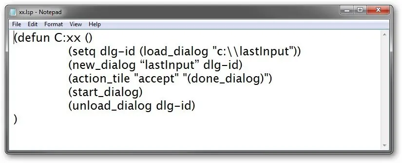
The following LISP code is what you use to load, run, and exit the lastInput.dcl dialog box definition file:
(defun C:xx ()
(setq dlg-id (load_dialog "c:\lastInput"))
(new_dialog "lastInput" dlg-id)
(action_tile "accept" "(done_dialog)")
(start_dialog)
(unload_dialog dlg-id)
)
To see what the LISP code means, let's take it apart.
The function is defined as "xx" with LISP's defun function. Programming = debugging, so I like to use an easy-to-enter name for the LISP routine, like "xx."
(defun C:xx ()
The lastInput.dcl file is loaded with the load_dialog function. There is no need to specify the ".dcl" extension because this is the sole purpose of this function: to load DCL files.
In Windows, include the name of the drive, C:\. Recall that LISP requires you to use \ instead of \ for separating folder names.
(setq dlg-id (load_dialog "c:\lastInput"))
In Linux, leave out the name of the drive:
(setq dlg-id (load_dialog "lastInput"))
DCL files can contain more than one dialog box definition, and so the next step is to use the new_dialog function to tell BricsCAD which one you want to access. In this case, there is just the one, "lastInput."
(new_dialog "lastInput" dlg-id)
The dialog box contains a button named "okButton," and its purpose is defined by LISP --- not DCL! Here you use the action_tile function to assign an action to the "okButton" tile. The button's purpose in life is to execute the done_dialog function that exits the dialog box. In short, click OK to exit the dialog box. You can read this as follows: "the action for the tile named okButton is ...".
(action_tile "okButton" "(done_dialog)")
After all these preliminaries, the big moment arrives. The start_dialog function launches the dialog box and waits then for you to click its button.
(start_dialog)
As neat programmers, we unload the dialog box from memory with the unload_dialog function.
(unload_dialog dlg-id)
And a final parenthesis ends the xx function.
)
Testing DCL Code
You have enough DCL code to test it now, which lets you see how the dialog box is developing. To test the code, take these steps:
Open Notepad, Text Edit, or another ASCII text editor.
Enter the DCL code we developed earlier:
 Important: Ensure that this DCL file and the LSP file use straight quotation marks that look like this: ". If they contain curly quotation marks ( " or " ), the routines will fail. LISP will complain, "error: bad argument type ; expected " while DCL will put up a dialog box complaining, syntax error: unexpected "".
Save the file as lastinput.dcl. So that the LISP xx.lsp routine can find it easily, save the file in a top level folder:
- In Windows, save the DCL file to the C:\ drive.
- In Linux and Mac, save the DCL file to your home folder. For example, I log in to Linux with the user name of "ralphg," so I saved the file in the ralphg folder.
Now, open a new file, and then enter the LISP code described in the "LISP Code to Load and Run Dialog Boxes section."

Save the file as xx.lsp, also in the same folder as the DCL file.
Switch to BricsCAD and then open the xx.lsp file in BricsCAD:
In Windows, use Explorer to drag the xx.lsp file into the BricsCAD drawing window. (Dragging the file is a lot faster than entering the AppLoad command or using the LISP load function!)
In Linux, you have to use the load function, because files cannot be dragged into the Linux version of BricsCAD. Enter the following at the ':' prompt:
: (load "xx")
Type xx to run the routine, which then loads the dialog box:
: xx
Notice that the dialog box appears! Well, it should, if you haven't made any coding errors.
What's Next?
In the next post, we'll look at how to add all the bells and whistles to your dialog box.


