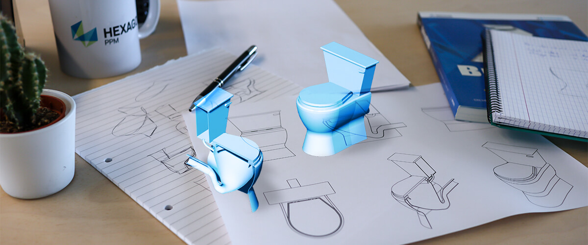
Practical guide how to draw a toilet in CAD
Last time I showed you how to make a sink in BricsCAD. This week I will be showing you how to draw a toilet in CAD. We'll be using most of the techniques you've already learned, to move your CAD drafting to the next level. Be sure to check bathroom part 1 and part 2 if you get stuck.
New commands covered:
- DMSIMPLIFY
- Extrude -- taper
- DMTHICKEN
- ISOLATEOBJECTS
- HIDEOBJECTS
- UNISOLATEOBJECTS
- SolidEdit -- Body -- seParate
- Components library (BricsCAD Mechanical only)
The Body
This week it's a little more complicated, but hang in there. I promise it's worth it.
The u-bend and bowl
I began by creating the u-bend and toilet bowl, using align, loft, simplify and shell.
To do this:
- Set up the outlines for your toilet.
- Use ALIGN to create the lofting shape of your toilet bowl.
Scale entities based on alignment points: Yes.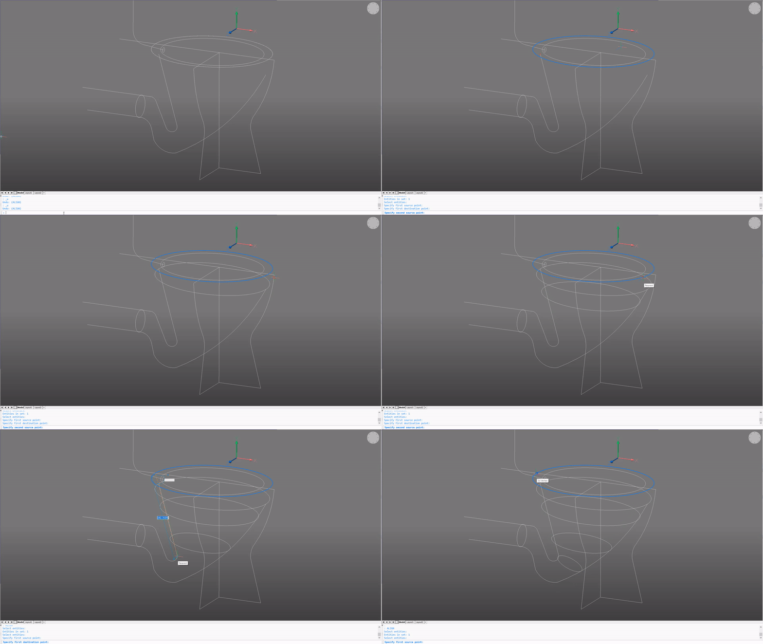
- LOFT the curves.
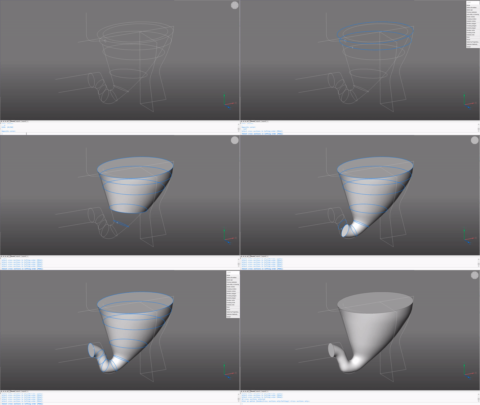
- Use DMSIMPLIFY. Select the solid.
- Use SolidEdit -- Body -- Shell. Select the flat, top and side faces to remove. Offset distance: 1.
It will now look a bit like an old-fashioned, clay pipe.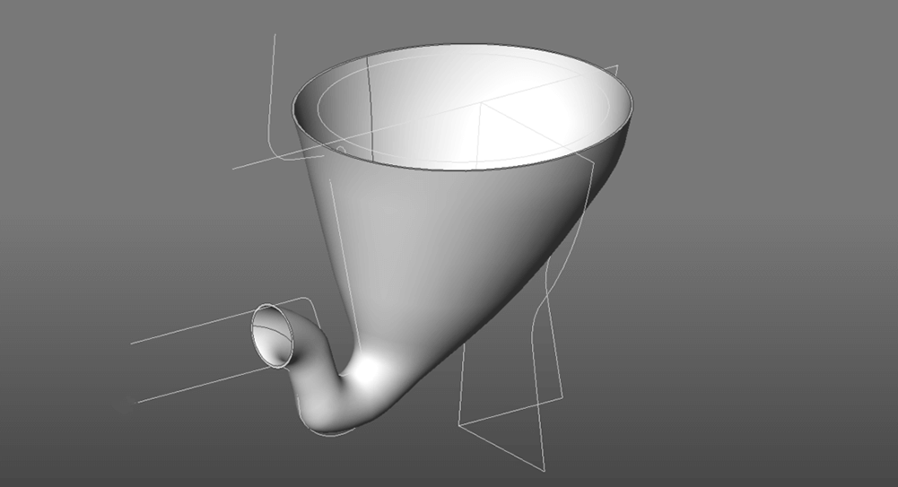
- Extrude the face of the exit of the "pipe".
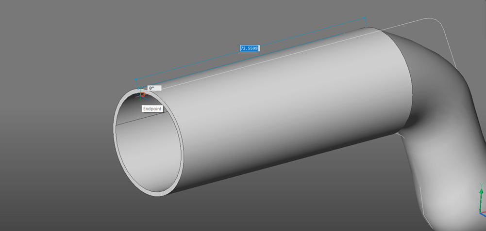
- Now the toilet bowl is complete. Hide it to keep the drawing tidy.
The main body
Next, I created the main body using revolve, extrude (taper), fillet and shell.
To do this:
- Create a closed, polyline in the shape of the toilet profile.
- REVOLVE the polyline. Angle: 180°.
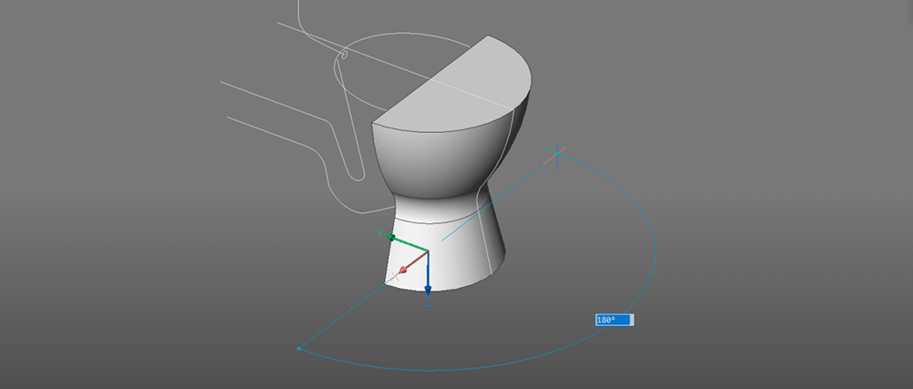
- Extrude the flat face with a taper. Distance: 75. Taper: 5°.
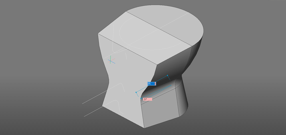
- Select the angled surfaces and hit Delete to flatten the top and bottom surfaces.
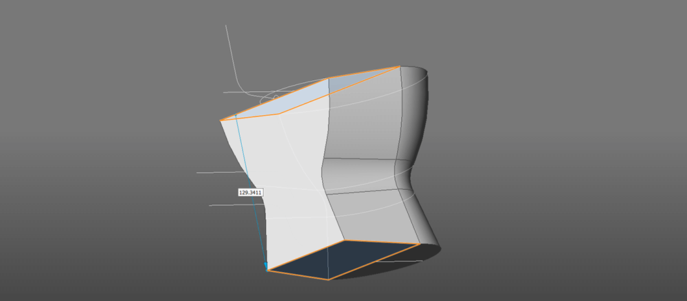
- Extrude the flat, back surface again. Distance: 60.
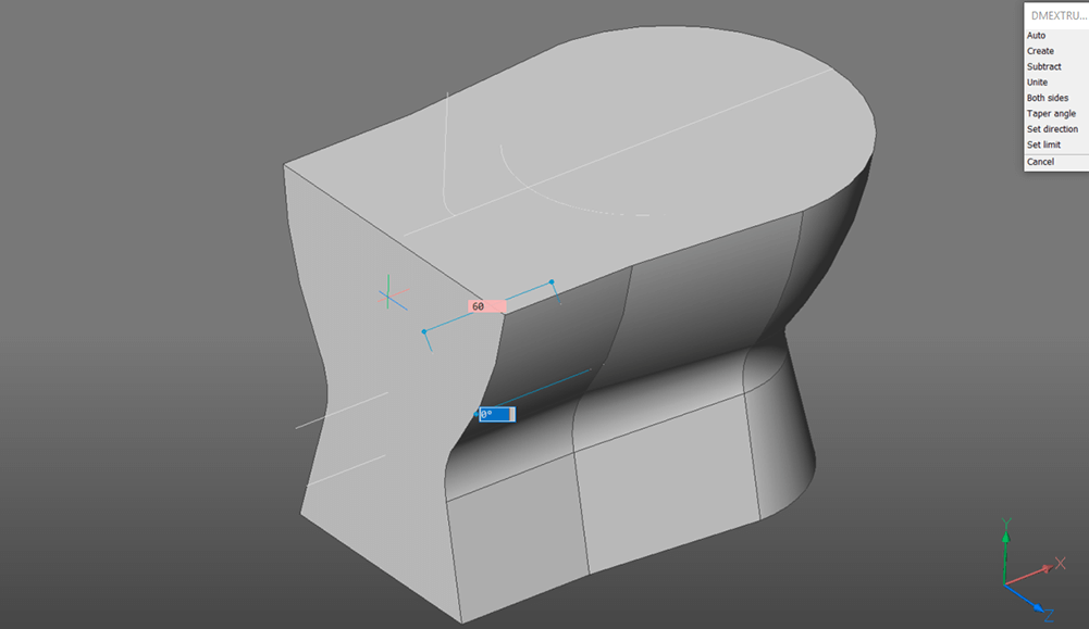
- Extrude the top surface. Distance: 10.
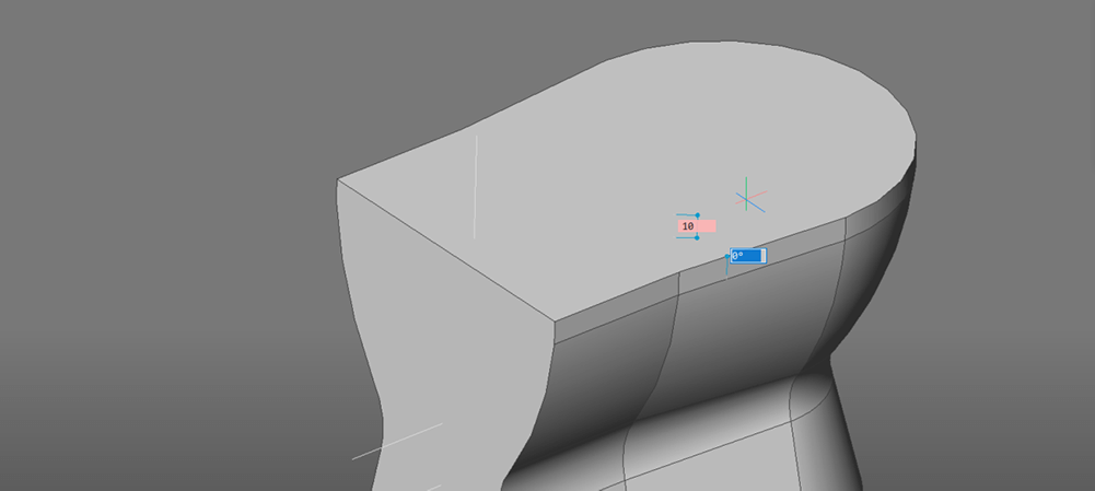
- Draw a polyline or spline in the shape of the bowl opening on the top surface.
Note: Ensure that the hole is smaller than the toilet bowl we just created. - Extrude down. Distance: 15. Taper: 20°.
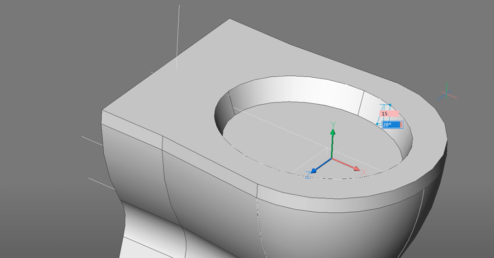
- Fillet the edges. Radius: 5.
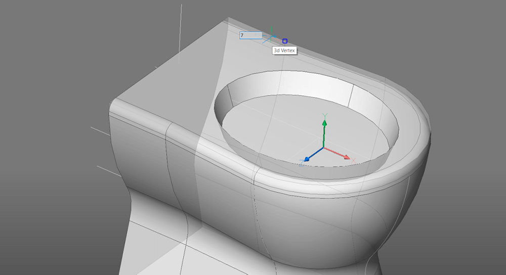
- Use SolidEdit -- Body -- Shell. Select the bottom face, back face, and the hole for removal. Distance: 1.
The result should be similar to the image below.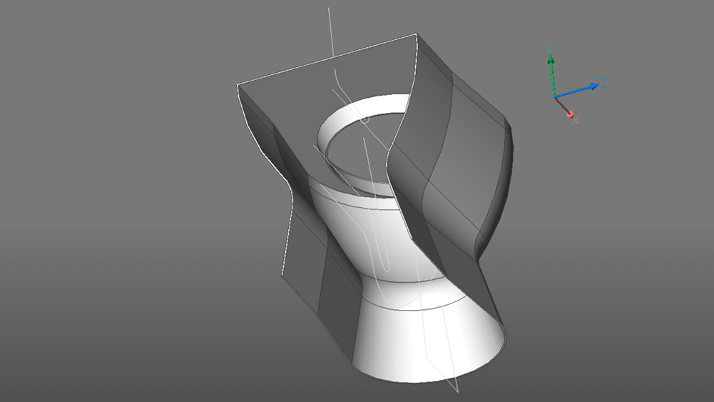
Union
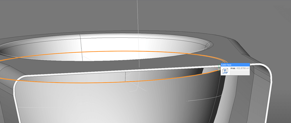
Once I had created both parts, I needed to fit them together. I simply extruded the top surface of the toilet bowl to the main body.
To do this:
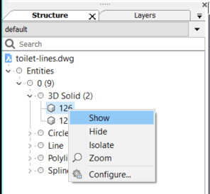
- Use the Structure Browser. Show the toilet bowl.
- Extrude top surface up to connect the 2 solids.
- Hide the solid.
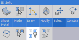
The tank
A toilet wouldn't be very useful without a water flow (until the dry toilet is perfected of course), so the next step was creating the tank and flow pipe. For this model I have oversimplified the design but feel free to let your imagination go wild.
I created a flow piper using thicken and shell. Then created a tank by drawing a line and extruding with a taper. Next, I offset the top and extruded again to create a lid. I shelled the tank, added a handle, filleted the hard edges, extracted the excess material and created a hole for the pipe to join the two portions of the toilet together. As a finishing touch, I used a cylinder and an extruded spline, to create a handle.
To do this:
- Use the DMTHICKEN on a polyline in the direction of the water flow.
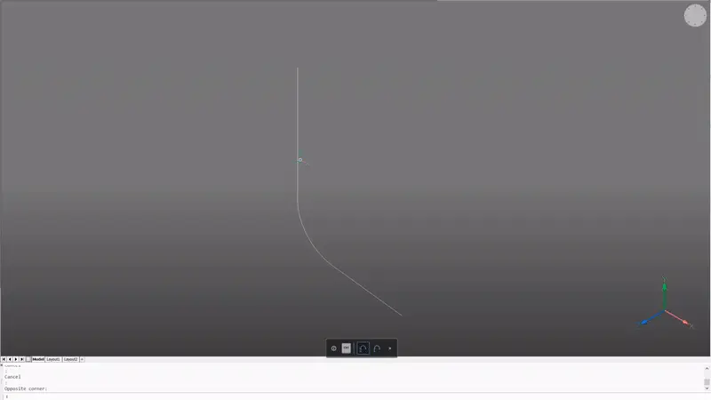
- SolidEdit -- Body -- Shell. Select the pipe shape and remove the two flat faces. Distance: 0.5.
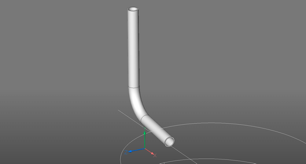
- Hide the tube.
- Use the Structure Browser. Show the first solid.
- Draw a line on the top of the toilet to mark the start of the tank.
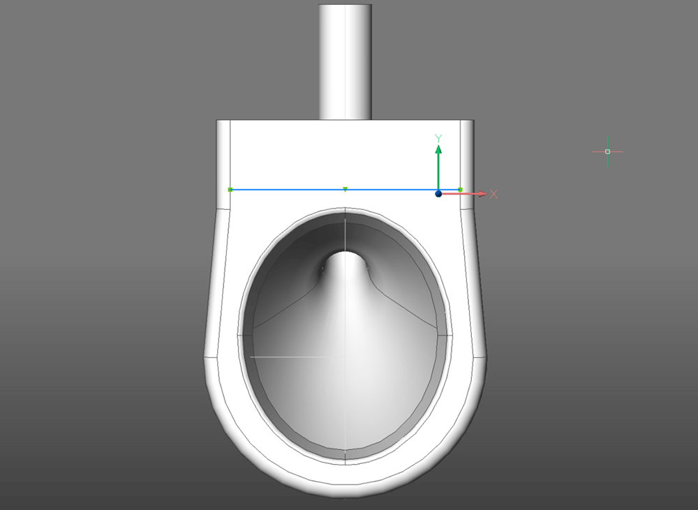
- Extrude boundary using the 'create' option. Distance 100. Taper angle: 15.
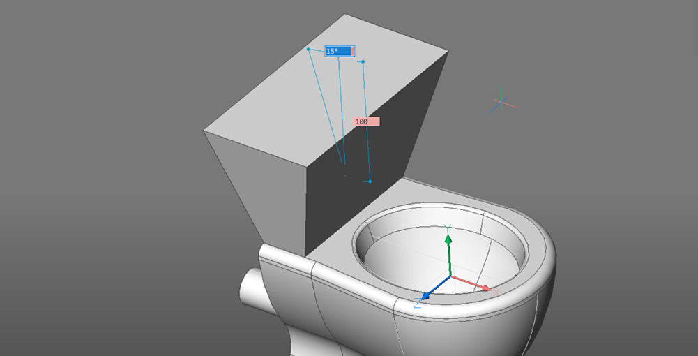
- Isolate this solid.
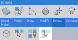
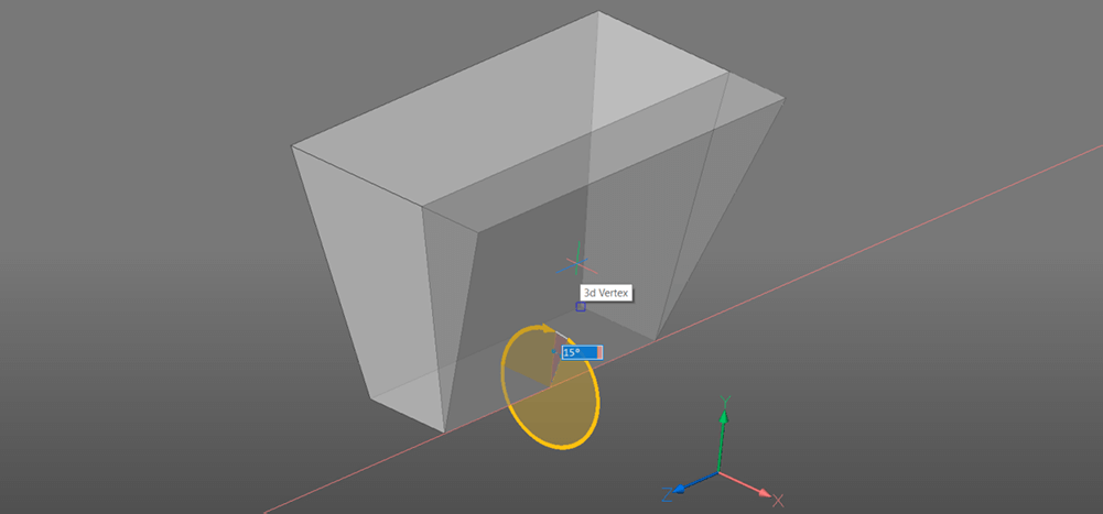
- Use the manipulator tool to flatten the front and back surfaces of the tank.
- OFFSET the edges of the top. Distance: 5.
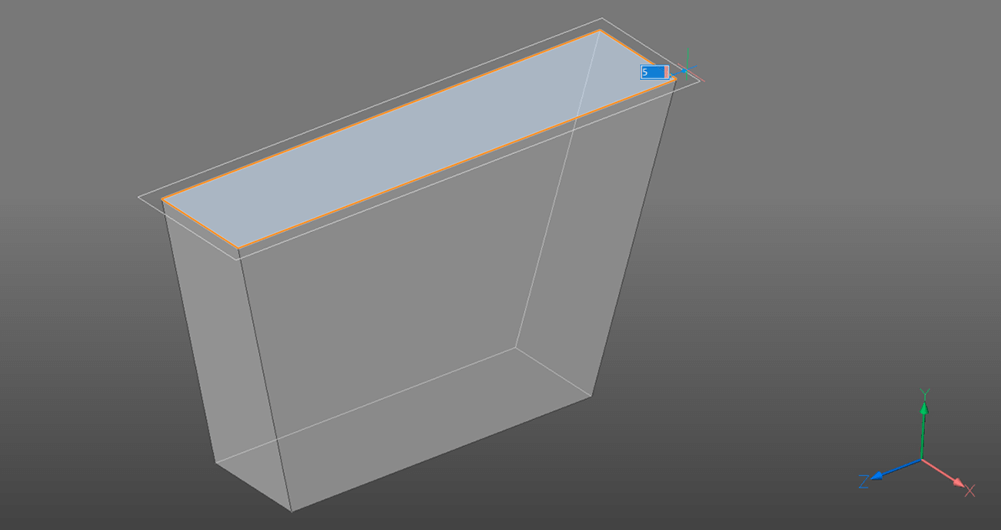
- Extrude the curve up using the 'create' option to draw a lid for the box. Distance: 6.
- DMFILLET the edges of the tank and lid. Radius: 2.
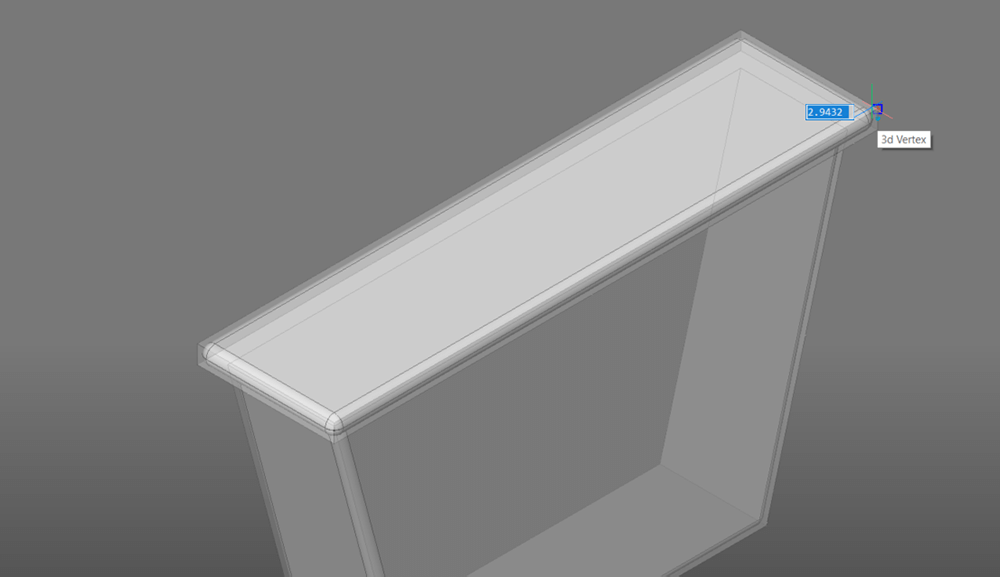
- Use SolidEdit -- Body -- Shell. Select the bottom solid. Select the top face for removal.
Tip: It's easier to do this if you hide the lid.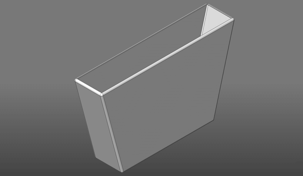
- Use CYLINDER to add a handle. Radius: 4.
Note: Hit Shift to fix the UCS to the face plane of the lid. The face will change blue. - Create a polyline on the surface of the cylinder in the shape of the handle.
- Extrude, 'unite' mode. Distance: 3.
If you get stuck: This is exactly the same as the technique used in Part 2.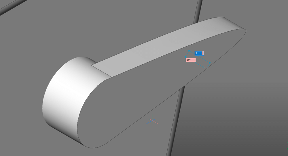
- Use the Structure Browser. Show the piping.
- SUBTRACT the pipe from the tank.
Note: If your pipe is deleted during this action check your settings. DELETETOOL should be "off". Value: 0.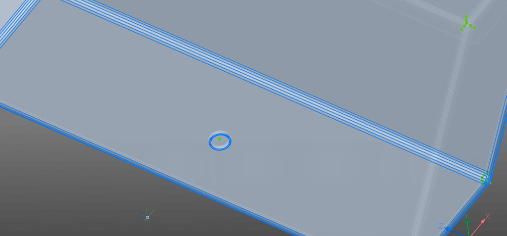
- The bottom of the tank will now have a hole cut into it, but will still be "one solid" in the Structure Browser. To fix this use SolidEdit -- Body -- seParate. Select the tank and hit Enter.
- Delete the excess material.
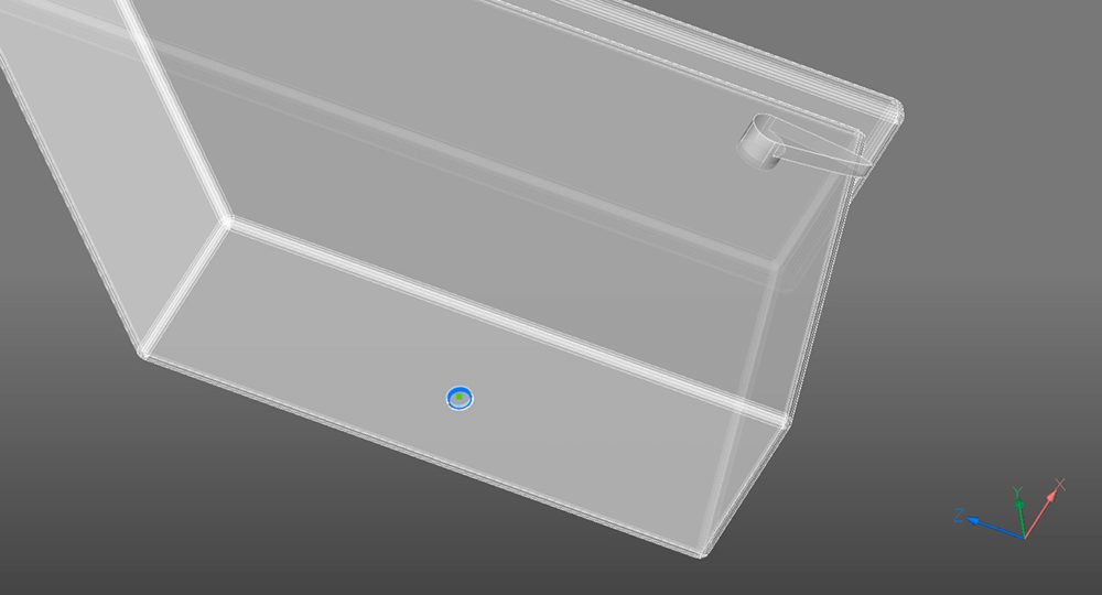
- UNISOLATEOBJECTS to show all entities.
- Repeat steps 17-19 to remove the material from the main toilet body.
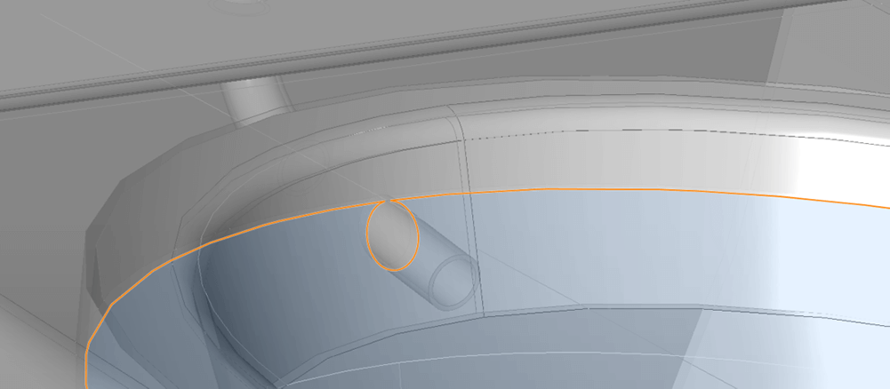
- DMPUSHPULL select the flat face of one end of the pipe. Adjust the length of the piping. Repeat for the other end.
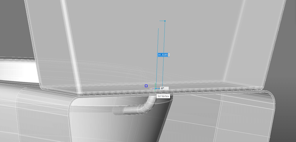
The results should be something like this:

The Seat
No toilet would be complete without a seat. I simply offset the edges of the hole, drew in the line-work, extruded the shapes and added components from my library to finish off.
To do this:
- Create a new layer. Set this as the new drawing layer. (a blue circle will be visible in the left column. This indicates the active layer.)

- Extract edges.
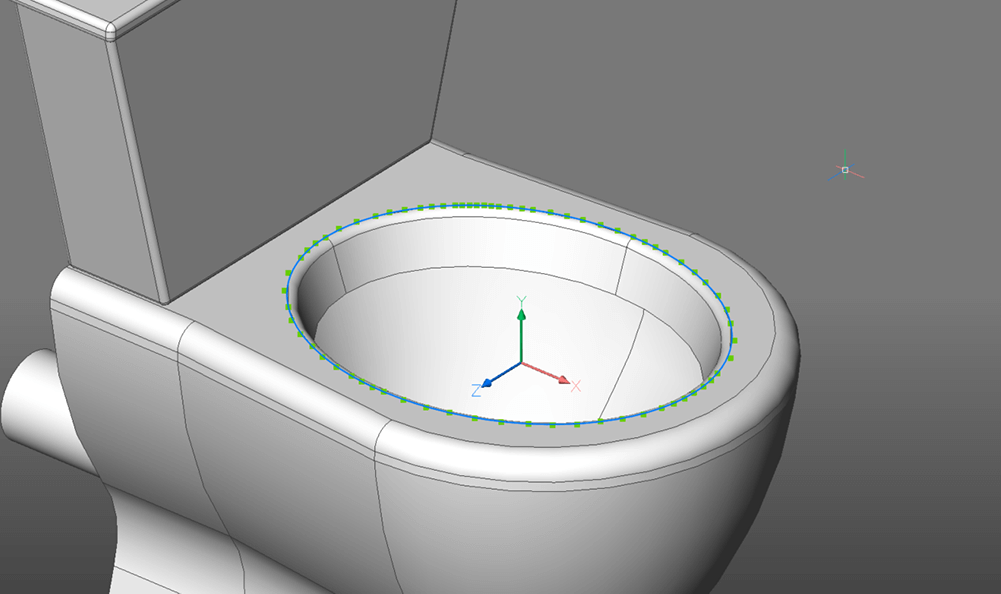
- Hide the original layer. Click the lightbulb on the layers panel.

- JOIN the extracted edges to one spline.
- OFFSET the spline in both directions. Distance: 8.
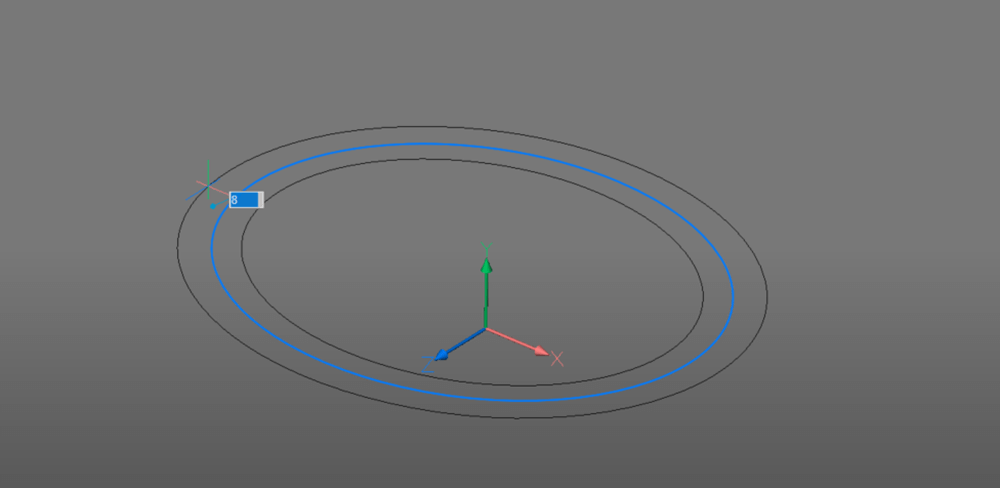
- Delete the original spline.
- Draw out your toilet seat shape.
Note: If you're not comfortable with 2D drawing commands yet, check out our lessons. - EXTRUDE the outer edge, up. Distance: 7. Taper: 5.
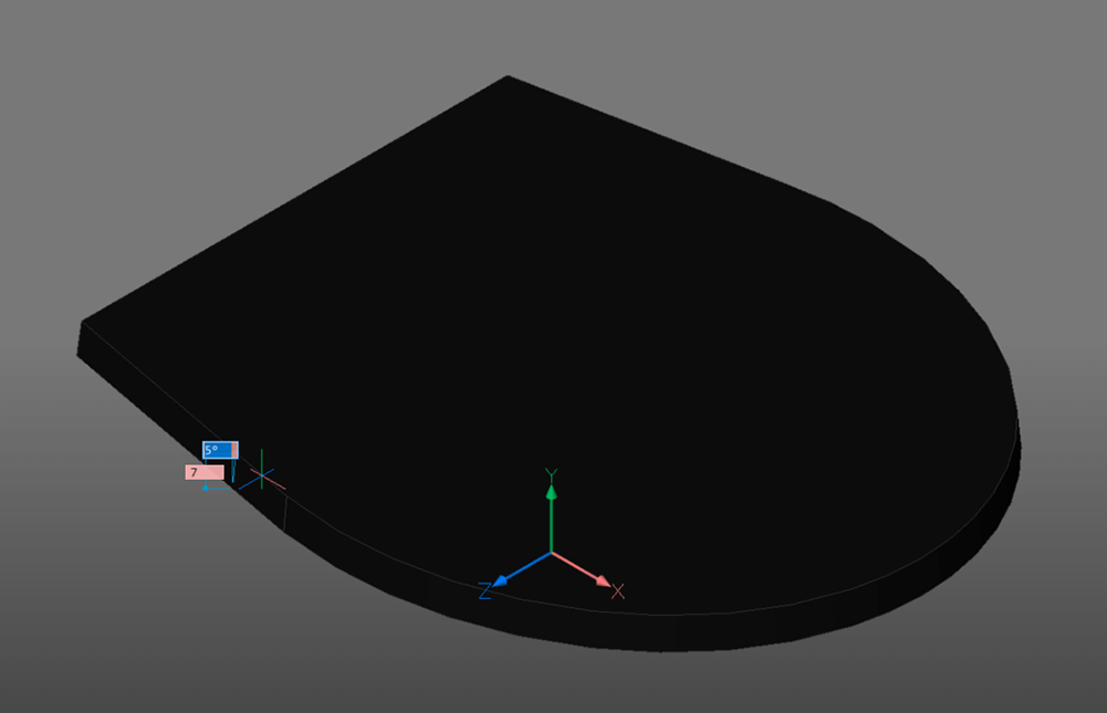
- OFFSET the top surface of the shape you just created.

- EXTRUDE this, up, use the 'create' mode. Distance: 7. Taper: 5.
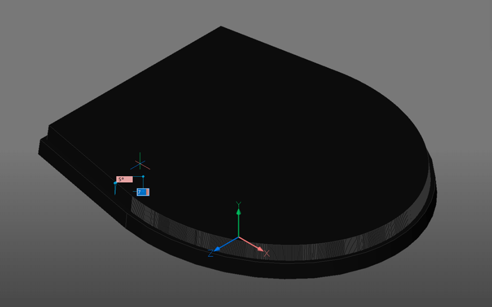
- Use the Manipulator tool to move this solid up. Distance: 2.
- Extrude the hole from the bottom portion of the seat.

- To finish use the Standard Parts Library.
Note: The screws are components from the standard parts library.
The hinge is a part I added to the library myself and I have used this on several projects. The screws are standard parts.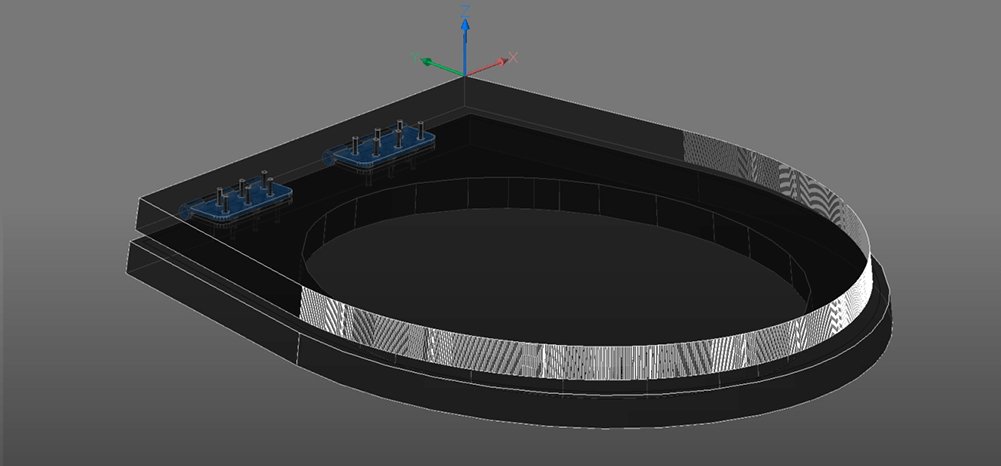
Finishing Up
Simply turn on all your hidden parts and you'll be able to admire your porcelain throne in all its glory.

Next time
Join me next time when I show you how to create the walls and floors of a building.
Don't have BricsCAD yet?
Easy to try, easy to buy, easy to own. That's BricsCAD. Try all of our products, for free for 30 days at www.bricsys.com. Freedom of choice, plus perpetual (permanent) product licenses that work with all languages, in all places. You'll love what we've built for you with BricsCAD.
Keep Reading
- Moving from 2D to 3D CAD
- 3D Drawing from engineering plans
- Drawing everything but the kitchen sink
- More Advanced Modeling
- The Shower
- The Sink
- The Toilet
- Walls and Floors
- The Roof
- Windows and Doors
- Create your own components
- Rubber Duck
- Laser-cut puzzle project
Note: This series is intended as a guide to demonstrate how to use different aspects of 3D modeling tools. It may not always demonstrate the fastest way of getting the result. Keep coming back to see if we cover a faster technique at a later date.
