Last time, I showed you how to create your own library of component parts. This time, follow along with a, laser-cut puzzle project. Learn how to convert solid entities into laser-cut ready objects.
Although some free tools exist that automatically split a 3D model into a laser-cut puzzle, they are not yet capable of extremely complex objects with many different angles. The model used in this project is an oversimplified example, however, the principles can be applied to far more complicated objects. The only limitation is your imagination!
Commands covered:
We're going to start off with a 3D model, if you don't have any you can download free CAD objects. For this project, you're going to want to start with a single solid. The simpler the shape the easier it will be to split up.
Converting a solid into a laser-cut puzzle
I began by splitting my object into slices, the extracting the faces and using DMThicken to convert the faces into solids. I repeated this action on a "cutting" layer and used these objects to generate the slots.
How to do this:
- COPY the entity as shown.
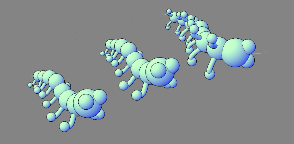
- Use the SLICE tool to split the solid as shown.
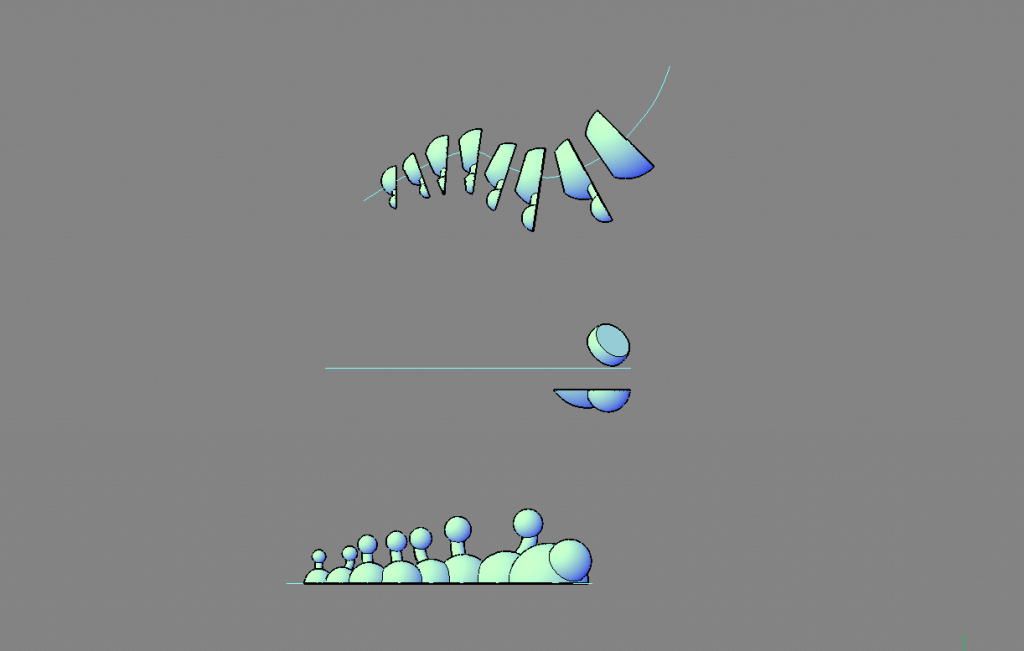
- Use XFACES to extract the face of each cutting plane.
- Delete the excess solids.
Tip: Use the entities panel to select and remove the solids. - COPY everything onto a new "cutting" layer.
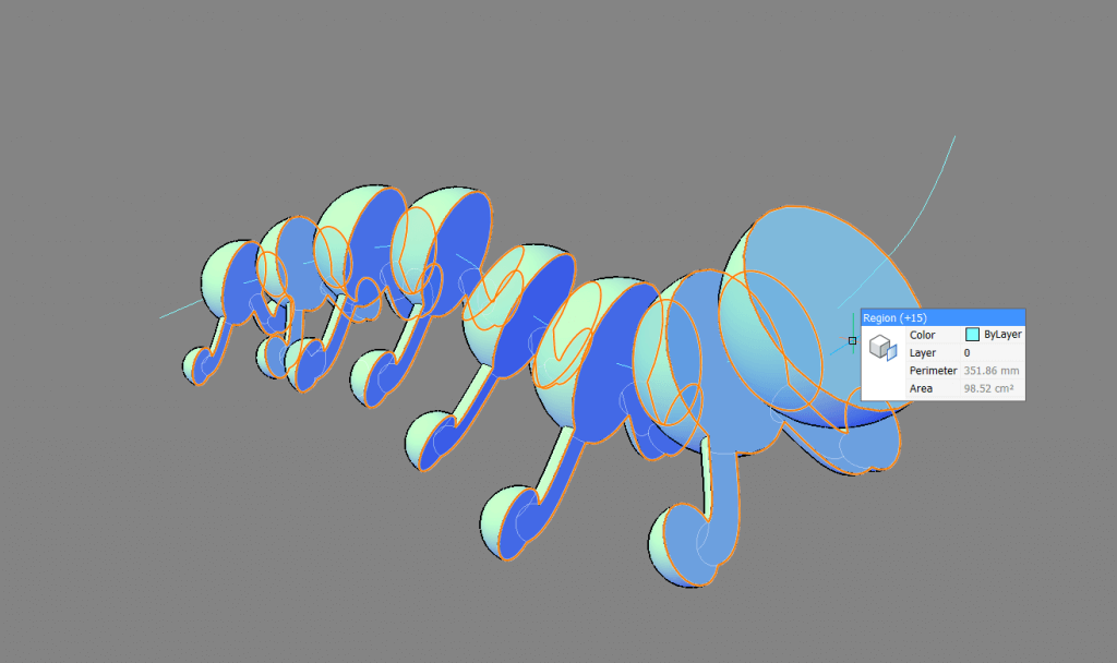
- DMTHICKEN the first set of regions. Distance: 2.5, both sides.
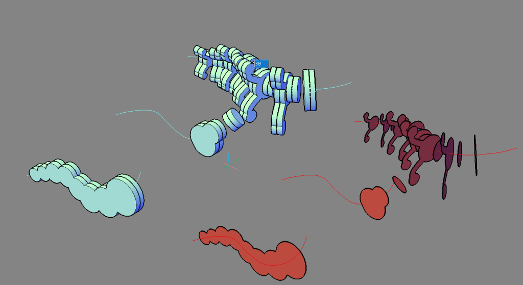
- Repeat on the cutting layer. This time with a distance of 2.6. This is to allow for tolerance on the slots.
- Delete all regions.
- EXTRUDE a surface from the centerline, through the cutting layer entities, as shown.
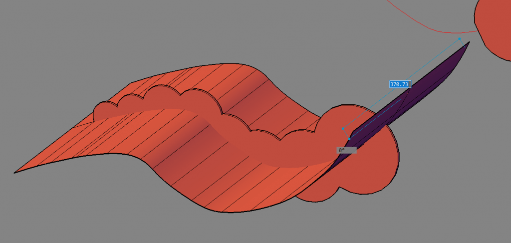
- Use this as a slicing object with the SLICE command.
- Repeat on all entities on the "cutting" layer.
You should now have something that looks like this:
- Seperate the sections, as shown.

- Move the cutting objects into position.
 Tip: Use the centerline snaping points to move everything into position. For best results, you will need to slightly offset the height that the cutting object meets the object to be cut out.
 - Subtract the cutting layer from the main layer.
The results should look like this: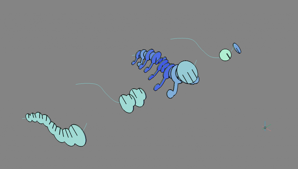 Note: Some of these slots are angled. Because laser cutters cut at 90 degrees, you will need to make some manual adjustments.
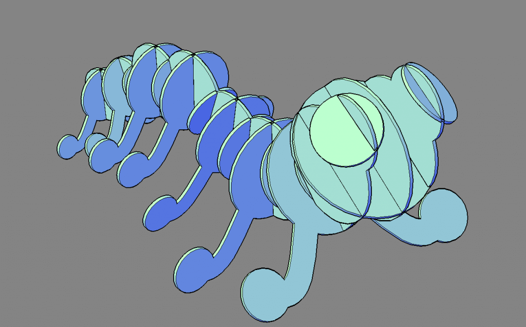
 - To finish your laser cut puzzle project, simply slot everything together.
Create the 2D file
A laser-cut -ready .dxf file can be created by simply arranging all the pieces and then hitting EXPORT.
Tip: Use VIEWBASE to create a top-down view automatically, no need to worry about making sure that all the objects are on the same plane!
Automatically generating laser-cut-ready files
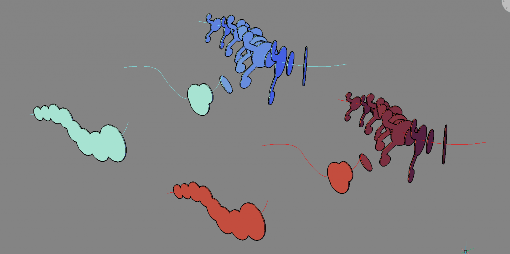
I tested this model on an automatic, laser-cut puzzle, generation software. Even when I spent a large amount of time adjusting the results, the software was unable to successfully generate a set of plans equivalent to that of above.

Model automatically generated using free software, due to the large number of angles at which the legs meet the body. Note the red pieces are not manufacturable.
Don't have BricsCAD yet?
Easy to try, easy to buy, easy to own. That's BricsCAD. Try all of our products, for free for 30 days at www.bricsys.com. Freedom of choice, plus perpetual (permanent) product licenses that work with all languages, in all places. You'll love what we've built for you with BricsCAD.
Keep Reading
- Moving from 2D to 3D CAD
- 3D Drawing from engineering plans
- Drawing everything but the kitchen sink
- More Advanced Modeling
- The Shower
- The Sink
- The Toilet
- Walls and Floors
- The Roof
- Windows and Doors
- Create your own components
- Rubber Duck
Note: This series is intended as a guide to demonstrate how to use different aspects of 3D modeling tools. It may not always demonstrate the fastest way of getting the result. Keep coming back to see if we cover a faster technique at a later date.



 Tip: Use the centerline snaping points to move everything into position. For best results, you will need to slightly offset the height that the cutting object meets the object to be cut out.
 Note: Some of these slots are angled. Because laser cutters cut at 90 degrees, you will need to make some manual adjustments.
