Creating custom line types in BricsCAD can significantly enhance the detail and clarity of your drawings. Whether you’re working on complex engineering plans or simple layout designs, understanding how to create your own line types can give your projects a professional edge. Follow this step-by-step guide to learn how to create both simple and complex line types in BricsCAD.
Step 1: Understanding Line Types in BricsCAD
BricsCAD software supports both simple and complex line types. Simple line types consist of lines, gaps, and dots, while complex line types can include text and shapes alongside simple line elements. These custom line types are stored in .LIN files, which can be edited or created as needed.
Step 2: Creating a New Line Type
- Open a Text Editor: Start by opening Notepad or any basic text editor of your choice.
- Write the Line-Type Definition: Each line-type definition consists of two lines of text. The first line, known as the header, starts with an asterisk (*) followed by the name of the line type (e.g., *TestLine), a comma, and then a description of the line type. You can also include an illustration of the line type in the description if necessary.
- Define the Line-Type Pattern: The second line of the definition starts with the letter 'A' (which stands for alignment flag), followed by a series of values defining the pattern of dashes, gaps, and dots. For example, you might specify a dash length of 3 units, followed by a gap of -2 units, and a dot represented by 0 units. This pattern can be repeated as needed.
- Save the .LIN File: Save your text file with a .LIN extension (e.g., TestLine.lin).
Step 3: Loading the Custom Line Type in BricsCAD
- Open BricsCAD: Start by opening your BricsCAD software.
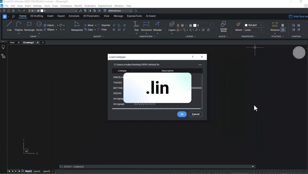
- Access the Line Type Manager: Go to the line type popup in the properties panel, click on "Load," and navigate to the location where you saved your .LIN file.
- Select and Load Your Line Type: Select your custom line type file and click "Open." In the load line types dialogue, your custom line type (e.g., TestLine) along with its description will be displayed. Select it and click "OK."
- Adjust the LT Scale if Necessary: If the line type doesn't display correctly, you may need to adjust the LT scale. Select the line, go to the properties panel, and set a higher value for LT scale.
Step 4: Creating Complex Line Types
For complex line types that include text or shapes, you will need to provide additional parameters within angular brackets. For example, specifying "PVC" within double quotes will display the letters PVC in your line type. You can also specify standard parameters such as the text style, height, rotation angle, and X/Y offsets for the text.
Step 5: Using Your Custom Line Type
- Draw with Your Line Type: With your custom line type loaded, you can now use it to draw lines or polylines in your BricsCAD drawings.
- Adjust the Line Type Scale as Needed: If the custom line type doesn’t look as expected, remember to adjust the line type scale for better visibility or to match your design specifications.
Whether you need simple dashed lines or complex patterns including text and shapes, BricsCAD’s flexible line type system has got you covered.
Watch the video!
Prefer video? Watch the tutorial on our YouTube channel to get the whole picture.


