2D parametric constraints are used to maintain relationships and control dimensions of 2D geometry. Here at Bricsys we're mad about Parametrics! You can find out more. 2D parametric constraints can be used to make multiple versions of a design without redrawing the object from scratch. This is super useful when working with blocks. Be sure to check back to the blog as we'll be covering this topic soon!
It's best practice to first apply geometric constraints, then dimensional constraints. But, don't panic if you don't, it (almost) always works out OK if you forget or change your mind about a constraint here or there. I do it all the time!
Geometric Constraints
Geometric constraints control the relationships between items.
 Parallel constraints are used to ensure that the sides remain parallel when one point is moved.

Here parallel constraints are used.
Adding more constraints further dictates how the object behaves.
Adding a  perpendicular constraint maintains the perpendicular relationship between sides. This changes the behavior of the object when a point is manipulated.

A perpendicular constraint has been added.
There is often more than one way of constraining a drawing to get the same results so you might want to try a few things.

Left: constrained with sides parallel and the bottom left corner perpendicular. Right: constrained to opposite, equal side lengths with the top right corner at 90°, both these constraints maintain the rectangular shape. However, the way they can be manipulated varies.
Coincidences control how separate items (for example polylines) remain connected at the same points. With BricsCAD it's possible to automatically create coincident constraints. Select  Coincidences -- Auto Constrain -- select all entities or choose specific ones and click Enter. This can be super useful when creating more complex objects. It's best to use Auto Constrain first, before adding other constraints, that way it's easier to check that everything connected the way you expected it to.
Dimensional constraints
Dimensional constraints are used to control the dimensions of an entity, such as length, angle, radius or diameter. They are my favorites because they don't just control length, they can control a whole load of things.
 Linear constraints keep things parallel, whilst
  horizontal and
  vertical constraints keep constraints horizontal and vertical respectively, all whilst maintaining distance.
 Aligned constraints are useful for lines that are drawn on a non-standard angle or for which a more specific relationship is not needed.
Dimensional constraints can be set as dependant on other constraints. This means that when you change the value of one constraint, other constraints change proportionally automatically.

Here the circle remains in the center of the box because the constraints applied from the side of the rectangle to the center of the circle are length/2 and width/2.
 Angle constraints are useful for things like doorways and rotating objects.

This door was created as a dynamic block and can be resized and re-oriented to fit the drawing requirements.
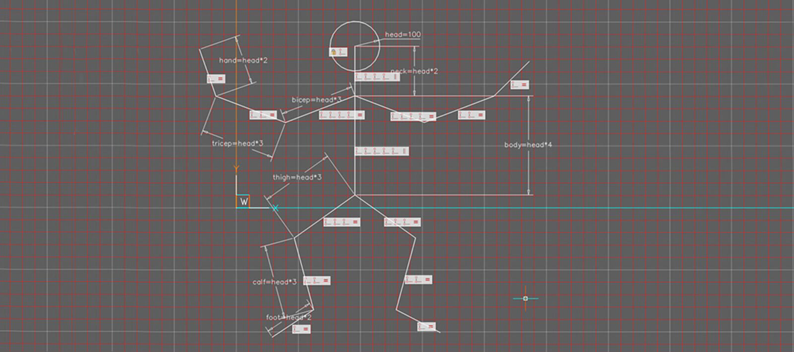
At times constraints might look a little overwhelming, but they're pretty simple. In the example below I used Auto Constrain to maintain the connections at the endpoints of the polylines, then constrained the arm and leg joints to be the same length on both sides, and finally, made all distances proportionate to the head's radius.

The constraints here mean is that the head arms and legs remain in proportion regardless of the position and size.
Editing Constraints
Use the Properties and Mechanical Browser panels to edit and manage your constraints.
In the Properties panel you can rename constraints to something more meaningful. E.g. "length", or "left corner". You can also change the value numerically or formulaically. For example: length = 20, or length = width/2. The later would mean that if the width was changed to 20 the length would automatically become 10.

to the right: the properties panel, click the small, grey fx box to show the formula. To the left, the constraint values in the browser panel, use the table to the bottom left to edit the values.
You can also change the value to a variable such as "x". Right click on the Mechanical Browser panel -- Add new parameter. You can then set the value of "x" for example radius+20 This can be useful for polar arrays. Who knew that high-school algebra would turn out to be useful after all?

By adjusting the radius, I can change the number of seats around the table automatically using parametric blocks.
You can also automatically clean-up constraints with Delete Unused Parameter or delete all constraints with Delete 2D Constraints.
Lost in Constraints
 Geometric and
  dimensional constraints can be toggled to view
  on and
  off independently with the show/hide commands. You can also choose to hide specific constraints if they are getting in the way. When you select an object the constraints applied to it will appear, even when all constraints are hidden.
Don't forget: You can always use Tab to switch between selections whilst hovering over layered objects.
If you need to see what constraints are applied to a given object, hover over the square, constraint icon, on the drawing. It will turn blue. A small white cross illustrates the constraint point, whilst the constrained items are displayed as dotted lines.

Hover over a constraint box to visualize the constraint.
And maybe best of all, you can animate the constraints to see how it affects the object. Right click on the constraint in the Mechanical Browser panel and select Animate.

He's so happy about constraints he's jumping for joy.
We're only scratching the surface here. For a complete list of all constraints and what they do, check the help pages.
Ready to get drawing?
Easy to try, easy to buy, easy to own. That's BricsCAD. Try all of our products, for free for 30 days at www.bricsys.com. Freedom of choice, plus perpetual (permanent) product licenses that work with all languages, in all places. You'll love what we've built for you with the BricsCAD product family.


