In this post, you will learn how to customize the Tool Palettes and Structure panels
The purpose of the Tool Palettes panel is to provide access to collections of commands and drawing elements you use often, such as specific hatch patterns. Instead of rummaging through a variety of commands and dialog boxes, you drag commonly-used items from this centralized palette into the drawing.
The purpose of the Structure panel is to show you the structure of the drawing: which entities are connected to which. You can customize the way it displays the structure.
PANEL COMMANDS AND VARIABLES
RELATED COMMANDS
StructurePanel and StructurePanelClose --- open and close the Structure panel displaying tree structure of the drawing content StructurePanel opens the Structure Tree Configuration File dialog box, prompting you to select a .cst (Configure Structure Tree) file; when you click Open, the Structure panel is opened and displays the configuration defined by the .cst file.
ToolPalettes and ToolPalettesClose --- opens and closes the Tool Palettes panel
-ToolPanel --- shows, hides, and toggles the visibility of specified panels through the command line
TpNavigate --- loads tool palettes and groups through the command line
RELATED SYSTEM VARIABLES
ToolPalettePath --- specifies the path to the folder holding .xtp files
TpState --- reports whether the tool palettes panel is open (read-only)
StructureTreeConfig --- specifies the CST file to use to configure the Structure panel
RELATED FILE TYPES
CST --- files that configure structure trees
XTP --- files that stored Tool Palette data, short for "xml tool palette"
About the Tool Palettes Panel
A most useful tool to CAD operators and managers is the Tools Palettes panel. To show you what the Tool Palettes panel looks like, the three default ones are illustrated below. From left to right, we have one filled with 3D form features, the next with commands, and the last with hatch and fill patterns.

Left to right: Palettes provided by default in BricsCAD
Here is how you work with the icons shown by each palette:
- Form Features tab --- drag a feature onto a sheet metal part
- Command Tools tab --- click an icon to run the associated command, such as the Line command
- Hatches tab --- drag one of the hatch or fill pattern icons into a closed object in the drawing
The Tool Palette panel is displayed by pressing Ctrl+3 (Cmd+3 on the Mac) or by entering the ToolPalettes command. It shows the same group of palettes in every drawing that is opened. Indeed, BricsCAD has the ability to provide one set of standardized of Tool Palettes for an entire office.
ToolPalettes does not, unfortunately, support blocks. Instead, use the Components panel with the ComponentsPanelOpen command.
(Form features are sheet metal features that mimic applying a forming tool to the sheet metal, such as bridges, louver, and embosses. They inserted from built-in or user-defined libraries; BricsCAD recognizes form features in imported geometry. Form features are listed in the Mechanical Browser pane with their parameters; they can be edited directly or parametrically through Properties panel. Each feature is represented by a .dwg file in the C:\Users\userid\AppData\Roaming\Bricsys\BricsCAD\V20x64\en_US\Support\DesignLibrary\SheetMetal\FormFeatures folder.)
The user interface of the Tool Palettes panel is subtle, with numerous options "hidden" in shortcut menus all over the palette. So, a large part of this chapter exposes these shortcut menus to you.
TIP You can use the right-click menu to add components from files listed in the Folders tab of the BricsCAD Drawing Explorer to the current tool palette.
QUICK SUMMARY OF VIEW OPTIONS
The View Options dialog box controls the size and style of icons. To access the dialog box, right-click the current tab in the Tool Palettes, and then choose View Options from the shortcut menu.

Adjusting the look of palette icons
Image Size --- slider changes the size of the icons, from smaller to larger
View Style --- switches between showing icons with labels (text), or showing icons only, or or text-only
Apply to --- applies the changes to the current tab or to all tabs
The figures below shows the effects of the Image Size and View Style options. Here is the smallest icon size, with text labels:

Small icons with labels
And here you see large icons with no labels. Removing labels squeezes in more icons, but may make it harder to know the purpose of them.

Large icons with no labels
Navigating Tools Palettes
Different shortcut menus appear in the Tool Palettes panel, depending on which tab you right-click. I recommend that first off you right-click the tab of the current palette, because it displays the largest number of options, and so is the most useful:

Right-clicking the current (or top-most) tab
Clicking one of the other tabs gets you an abbreviated version. Here is the meaning of the options:
View Options displays a dialog box for setting the size and look of icons, along with descriptions.
Paste pastes data from the Clipboard into the palette; available only when the Clipboard contains data appropriate to the Tool Palette, such as a block definition.
Update Palette updates the image of the icons, should a source (like a block definition) have changed.
New Palette creates a new blank tab.
Delete Palette removes a tab.
Rename Palette renames the selected tab; see figure below:

Renaming a tab
ICON CUSTOMIZATION
When you right-click a tool's icon, BricsCAD shows the following shortcut menu. Depending on which icon you right-click, the shortcut menu may show fewer options:

Shortcut menu for individual tools
Cut and Copy --- place the tool on the Clipboard (Cut also deletes it from the palette); you can then right-click the palette and select Paste
Delete --- removes the tool.
Rename --- allows you to rename the tool, as shown below

Renaming a tool
Update tool image --- refreshes the icon (applies to blocks and hatch patterns only)
Specify Image --- opens the Select Image File dialog box, from which you select an image in BMP bitmap, GIF, JPEG, PNG, or TIF format -- large images are resized automatically to fit the icon area
Remove Image --- returns the icon to its default, removing the image you applied with the Specify Image option.
Properties --- displays a dialog box for changing the item's properties (see figure below); the content of the dialog box varies according to the type of tool selected, and is discussed later in this post.

Changing the properties (and functions) of a tool
Shown above are the properties of hatch patterns. To edit a property, click on it in the dialog box and then make the change.
PALETTE CUSTOMIZATION
The first step in customizing the Tool Palettes panel is to right-click on an unused area of the panel --- not on an icon or a tab --- to get the following shortcut menu:

Right-click menu for controlling palettes
View Options --- displays the same dialog box as does the tab's shortcut menu
Paste --- pastes a tool, if one has been copied or cut to the Clipboard
Update tool image --- refreshes the icon (applies to blocks and hatch patterns only)
New Palette --- adds a new blank palette
Delete Palette --- removes a palette
Rename Palette --- changes the name on the tab
Customize Palettes --- displays the Customize dialog box for creating palette groups (see figure below); the dialog box is described later

Customize dialog box for creating palette groups
Add Tool --- displays the Customize dialog box.
Customizing Tools
The Tool Properties dialog box lets you customize the actions of commands and hatch patterns. For instance, you can specify that clicking an icon (that looks like a cloud) draws revisions clouds that are red in color, and placed on a specific layer or with a certain linetype.
To access this very important dialog box, right-click the icon you want to customize and then choose Properties. There are three versions of the dialog box --- one each for form features (components), hatches, and commands, as illustrated below:

Left to right: Tool properties for form features, patterns, and all other commands
Customizing Tools Properties
In this tutorial, you make a copy of an existing tool and then customize it by changing its properties.
You modify the Line tool to draw lines with the "Hidden" linetype on layer "Hidden."
Follow these steps to customize it:
Create a new layer named "Hidden." Use the Layer command to do this in the Drawing Explorer dialog box.

Creating a new layer named "Hidden"
Load the "Hidden" linetype into the drawing. Use the Linetype > Load option for this.
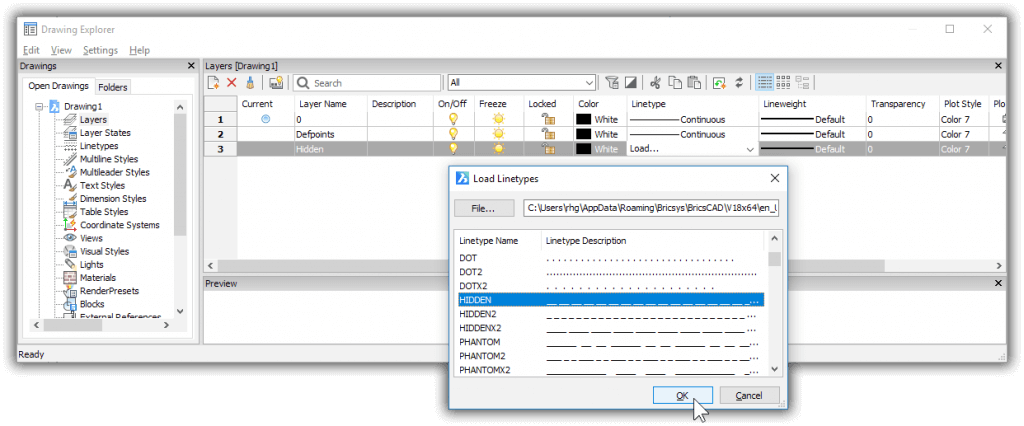
Drawing Explorer listing available linetypes.
Close the Drawing Explorer.
Open the Tool Palettes panel with the ToolPalettes command and then choose the Command Tools tab.
Make a copy of the Line tool by copying it and then pasting it, like this:
Right-click the Line tool and then choose Copy from the shortcut menu.
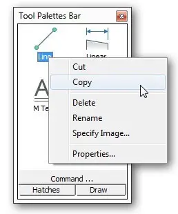
Copying the Line tool
Right-click a blank area of the palette and then choose Paste.
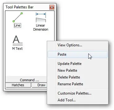
Pasting the tool as a new one
Notice that BricsCAD creates a second Line tool.
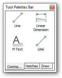
The second Line tool in place
With the copy made, you can now edit its properties. Right-click the new item, and then choose Properties.
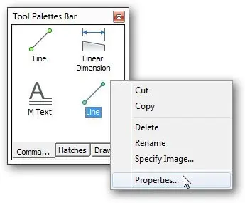
Opening the properties of the new Line tool
In the Properties dialog box, change the following properties for this tutorial:
Name Hidden Line
Description Draws line with linetype Hidden on layer Hidden
Linetype Hidden
Layer Hidden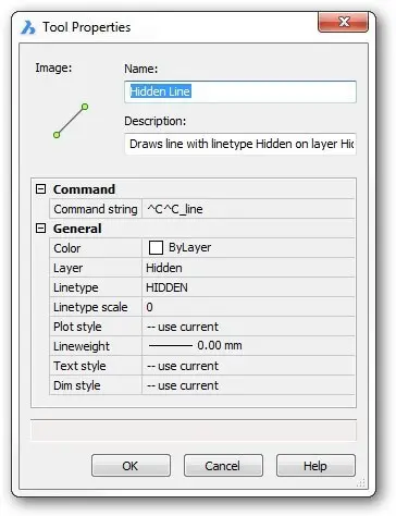
Changing the properties
Click OK. Notice that BricsCAD changes the label of the icon.
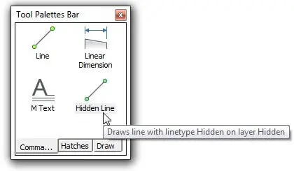
Renamed icon
If you want to change the icon associated with the button, follow these steps:
Right-click the icon and then from the shortcut menu, choose Specify Image.
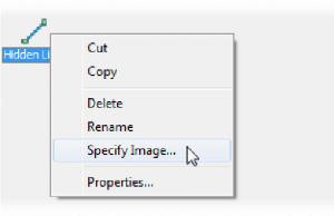
Starting to assign an image to the button
In the Select Image Position File dialog box, select an image file (in BMP, JPEG, PNG, GIF, or TIFF format) and then click Open. Notice that the icon changes. BricsCAD automatically resizes the image to fit the area of the icon.

Icon changes to the newly selected image
To test the tool to make sure that it actually works, click it and draw some line segments. If you do not see the hidden linetype, change the value of the linetype scale with the LtScale command.

Drawing line segments with hidden linetype automatically applied
After drawing the lines, click them to see that they are being drawn on the Hidden layer.

"Hidden" layer automatically set
Adding Programs and Macros to Tools
You can make tools carry out simple programs (known as "macros") but the process is less direct than with just commands. It takes a workaround shown by these steps:
Place any geometric entity (tool) on a palette. It doesn't matter what the entity is because it is used only as a placeholder.
Right-click the newly-added tool, and then select Properties.
In the Command String area, replace the command with a piece of programming code or a macro.

Editing the macro assigned to a button
TIP You can either type the new code, or copy'n paste it from another source, such as from the earlier chapters of this book that deal with writing macros.
- Click OK and then test to macro to make sure it works.
Organizing Tools with Groups
BricsCAD allows you to create many palettes, but too many palettes can become unwieldy and so BricsCAD allows you to create groups of palettes. Groups let you show only those palettes you need currently.
To create groups, right-click a blank area of the Tool Palettes panel, and then choose Customize Palettes from the shortcut menu.

Accessing that other Customize dialog box
Notice that the Customize dialog box appears and that it is different from the Customize dialog box displayed by the Customize command! (There is no independent command to display this dialog box.)

Dialog box for creating palette groups
The commands and options for this dialog box are accessed solely by right-click menus. For instance, to create a new palette, right-click in the Palettes area and then select New Palette, as shown above.
Rename --- renames the palette
New Palette --- creates a new palette named "New Palette," which you then give a new name
Delete --- erases the palette after you click OK to this dialog box:

Import --- imports palette files in XTP and BTC formats; opens the Import Palette dialog box. XTP is short for "XML Tool Palette," the file format used by AutoCAD®. BTC is short for "BrisCAD Tool Collection."
CREATING PALETTE GROUPS
You can create as many palettes as you want. I can see a design firm creating dozens of palettes, some for electrical engineers, some for landscape designers, and so on. You can create grouping of palettes so that the electrical engineer doesn't have to see the palettes for landscaping. A group is a smaller set of palettes.
BricsCAD does not come with any palette groups, so you get to create your own through the Customize dialog box ---this is not the dialog box of the same name that is opened with the Customize command.
There is no command to access this dialog box. Instead, you (as always) right-click a blank area of a palette and then choose Customize Palettes from the shortcut menu. Notice the other Customize dialog box:

Accessing that other Customize dialog box
(While this dialog box existed prior to V17, the groups function did not work.) As elsewhere with Tool Palettes, all commands in this dialog box are executed through shortcut menu. When you right-click the name of a group, the following menu appears:

Shortcut menu for palette groups
New Group --- creates a new but empty palette group
Rename --- renames the palette group
Delete --- erases the group (with no warning)
Set Current--- sets the selected group as the current one, meaning it will be displayed by the Tool Palette panel; when the group is empty, then this command is grayed out
Export --- exports the current group to a XPG file, as described later
Export All ---exports all groups in a single XPG file
Import --- imports XTP and BTC files, as described later
To create a group of palettes, follow these steps:
In the Customize dialog box, right-click Palette Groups and then, from the shortcut menu, choose New Group.
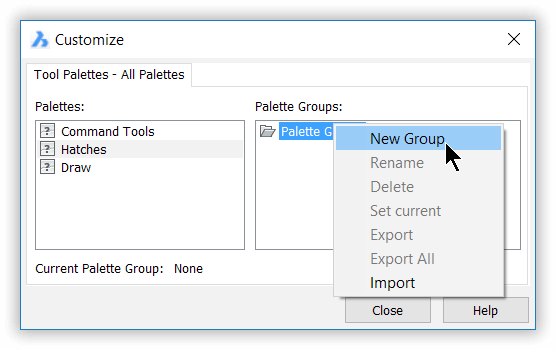
Creating a new group of palettes
Notice that BricsCAD creates a new group name named "New Group." For this tutorial, change the name to Drawing Lines.
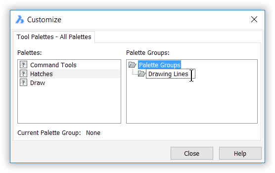
Naming the new group
Now drag palette names from the Palettes list over into the newly formed group. For this tutorial, drag over "Hatches."
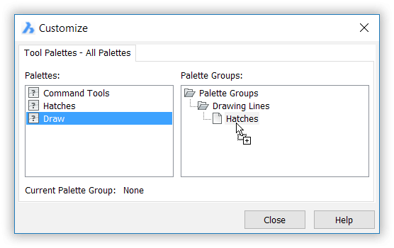
Add palettes to a group
Right-click the group "Drawing Lines" and then from the dialog box choose Set Current.
When done, click Close. Notice that the Tool Palette panel now shows just one palette: Hatches.
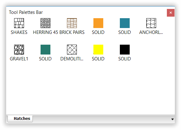
Tool palettes with a custom group that shows just one palette
IMPORTING TOOL PALETTES FROM AUTOCAD®
BricsCAD reads files saved the XTP format; this is the format in which AutoCAD® saves tool palettes. "XTP" is an XML-based file format; the name is short for "xml tool palette." To import them into BricsCAD follow these steps:
In this Customize dialog box, right click and then choose Import from the shortcut menu.
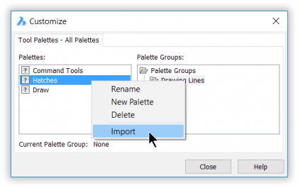
Choosing the Import option
In the Import Palette dialog box, navigate to where you have XTP files.
Choose the file and then click Open. Notice that BricsCAD adds the palette to its collection.
Click Close to close the dialog box. Notice the new tab with its icons.
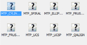
BricsCAD does not have access to the icons used for tools, because AutoCAD® stores them internally. This is why question-mark icons are displayed.
Sharing Tool Palette Groups by Exporting Them
Once you customize a tool palette, you might want to share it with others. To do so, you export groups. Groups are exported in XTG files (short for "XML tool group").
Individual palettes cannot be exported, but you can do the same thing by putting a single palette into a group and then exporting that.
Here is how to do this:
- In this Customize dialog box, right-click a group and then choose Export from the shortcut menu.
- In the Export Palette dialog box, navigate to where you store the XTG files.
- Name the file and then click Save.
Alternative Sharing Method
Another way to share palettes is to edit the Settings dialog box in BricsCAD to point to where BTC and XTP files are stored, such as for AutoCAD®.
Enter the Settings command.
In the search field, enter "palette."
Open the Tool Palettes section, and then go to the Tool Palettes Path setting.
Click the ... Browse button.
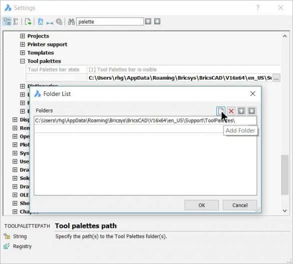
Adding folders to BricsCAD's folder searches
In the Folder List dialog box, click the Add Folder button.
Enter the path to the folder holding the XTP or BTC files. If necessary, click the Browse button and then use the Choose a Folder dialog box to locate the folder.
Click OK sufficient times to back out of all the folders!
This dialog box can be used to point to other AutoCAD® support folders, such as hatch pattern collections, linetype files, printer setups, and so on.
Customizing the Structure Panel
The Structure panel displays a structured tree view of the drawing's content. This includes the names of entities, blocks, and nearly any other entity. You can customize the elements that are listed and in which order.
When you select the name of an entity in the structure tree, the entity is highlighted in the drawing --- and vice versa. Notice that entities are identified by hexadecimal (base 16) numbers.

Structure panel showing the structure of a floor plan by entities
There are two commands to open the Structure panel:
- StructurePanel opens the Structure panel; StucturePanelClose closes it. Alternatively, right-click a toolbar or other UI element in BricsCAD, and then choose Structure from the shortcut menu.
- +StructurePanel opens the Structure Tree Configuration File dialog box, prompting you to select a .cst (Configure Structure Tree) file; when you click Open, the Structure panel is opened and displays the configuration defined by the .cst
Note: The panel operates in model space only.
When the panel opens, right-click the name of the drawing to see the following shortcut menu:

Accessing options
Drawing Properties --- displays the Drawing properties dialog box, the same as entering the DwgProps command
Export --- exports the drawing as an XML file
Expand / Collapse All --- expands and collapses all nodes
Configure --- displays the Configure Structure Tree (more later)
Right-clicking any other item in the panel displays the following shortcut menu, with a few different options:

Accessing another shortcut menu
Show --- Show the entity in the drawing
Hide --- Hides the entity from the drawing
Isolate --- Hides all other entities in the drawing
Zoom --- Zooms into the selected entity(ies)
Structure Configurations
The data displayed by the panel can be customized. BricsCAD provides several pre-made configurations suitable for various kinds of drawings. The C:\Users<login>\AppData\Roaming\Bricsys\ BricsCAD\V20x64\en_US\Support folder holds these .cst files:
default.cst
bim.cst
mechanical.cst
To load another configuration, click the down arrow (upper-right corner of the panel) and then choose one from the list or else navigate to another folder with the Select option.

Selecting a Structure panel configuration
Alternatively, enter the StructureTreeConfig variable, which prompts you at the command line to specify the name of a .cst file:
: structuretreeconfig
New value for StructureTreeConfig, or . for none/< C:\Users*<login>\AppData\Roaming\Bricsys\BricsCAD\V20x64\en_US\Support\default.cst>:*
CUSTOMIZING THE STRUCTURE PANEL
The format of the panel is customized through the Configure Structure Tree dialog box. You can create many configurations, depending on your needs. Customization of a configuration takes two steps:
Step 1 --- Create a rule
Step 2 --- Specify the properties of the rule
STRUCTURE OF .cst FILES
The C:\Users\userid\AppData\Roaming\Bricsys\BricsCAD\V20x64\en_US\Support folder holds several .cst files. The bim.cst file is shown below, organizing the building spatially, first by Building, then by Story, BIM type, and then composition. Sections are grouped by type: Section, Plan, Elevation, and Detail.
{
"created": {
"by": "BricsCAD",
"on": "2016-10-28 10:50:09"
},
"rules": [
{
"name": "Building Elements",
"group": [
"BIM/Building",
"BIM/Story",
"BIM/Type",
"BIM/Composition"
],
"sort": [
"BIM/Name"
]
},
{
"name": "Sections",
"group": [
"BIM/Section Type"
],
"sort": [
"Name"
]
},
{
"name": "Entities",
"group": [
"EntityType"
],
"sort": [
"Name",
"EffectiveName",
"Handle"
]
}
],
"mode": "showAll",
"some": [],
"options": {
"treeSelect": "select",
"entitySelect": true,
"autoCollapse": false,
"displayMode": "byType"
}
}
To customize the data displayed by the panel, click the bar (the one with the word "default" in the figure below).

Opening the Configure Structure Tree dialog box
This handy shortcut opens the Configure Structure Tree dialog box.

Dialog box for customizing the display of the Structure panel
The dialog box sports three tabs --- Group/Sort, Show/Skip, and Options. Let's take a look at what they offer.
Group/Sort Tab
The Group/Sort tab determines how drawing data is displayed. Here you can add rules and property filters, move items around, and remove them.
To add a rule:
- Select an existing rule name.
- Click the green + (Add) button. Notice that the rule is duplicated.
- Use the arrows to move the selected rule up and down the list.
- Edit the content of the rule, as described later.
To rename a rule:
- Select a rule name.
- Click on the name a second time.
- Give the rule a different name, and then press Enter.
To remove a rule:
- Select a rule name.
- Click the red x button (there is no warning).
Examining Rules
The way that element information is displayed in the Structure panel is determined by rules. The rules specify which entities are displayed and the order in which their properties are listed. By listing one property ahead of another one, the second property becomes a subset of the first. More on this later.
Let's take the example of the bim.cst configuration.

Left: Structure panel's display controlled by; right: ...the bim.cst file
The names of the rules --- such as Building Elements and Sections --- are for use by humans only and describe the content of the rules. Think of them as sections. Click a gray > (angle bracket) to open the section, displaying the elements of the rule.

Expanded rules
There are three elements in each rule:
Filter --- determines which elements are displayed by the rule; in this rule, it's the names of BIM Types.
Group --- determines how the BIM Types are grouped together; in this case, BIM Buildings, Stories, etc.
Sort --- specifies how the elements are sorted within each group; here, it's by BIM Name.
Let's look at another rule to assist with understanding how configurations work: information about sections. The Sections rule arrives at this by specifying the following:
| Rule | Property | Meaning |
|---|---|---|
| Filter | BIM Section type | List details, elevation, plan, and section names |
| Group | BIM Section type | Group together BIM section types |
| Sort | Name | Sort section types by name alphabetically |
You can see why I used the word "elements" instead of "entities."

BIM rules for displaying sections
TIP The Diff Type property is used during the 3dCompare command; it reports differences, if any, between the two drawings being compared. When there is no configuration file loaded, the Structure panel displays drawing entities in alphabetical order. The icon in front of each name identifies the entity type, such as polyline, circle, and text:
Constructing Rules
To construct a rule, you select properties from a long list that I will show you shortly.
For this tutorial, I created a blank configuration file. I did this by deleting all rules from an existing .cst file, and then used the File | Save As command to save it (with the name cb.cst).

Saving a blank .cst file
In this tutorial, we create a rule that causes the Structure panel to list only lines in the current drawing, sorted by layer name and then by length.
To start constructing a new set of configuration rules, click the + icon. Notice that a generic rule is added, named "Rule."
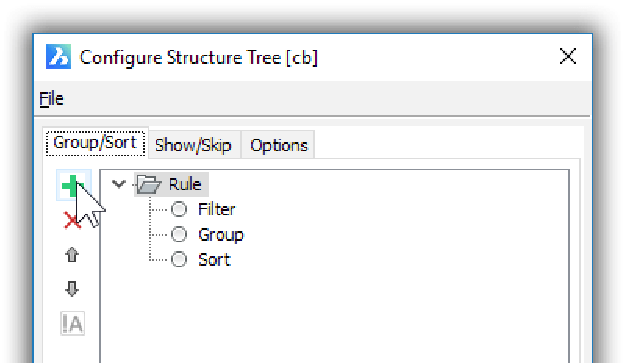
A generic rule added
The generic rule has three (fixed) sections that define the rule: Filter, Group, and Sort. You cannot add or delete these three sections. If the section is empty, then it does nothing.
Rename the rule as "Lines by Layer," as follows:
Right-click "Rule," and then choose Rename.
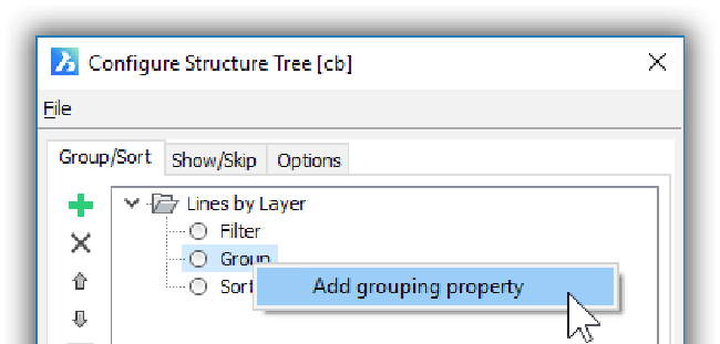
Adding properties to a rule
Change "Rule" to Lines by Layer and then press Enter.
We want the Structure tree to display only lines, so right-click Group and then choose Add Filter Property.

Adding properties to a rule
Notice the Select Property dialog box. It lists every property available in BricsCAD --- a couple hundred of them.
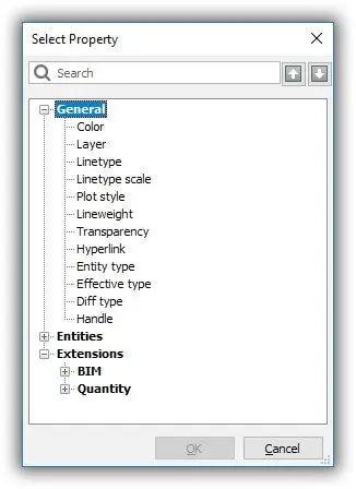
Properties dialog box
The properties are grouped into these sections:
- General --- lists properties common to all entities; these should be known to you from the Properties panel
- Entities --- lists the names of all entities and their specific properties
- Extensions --- lists properties that are specific to add-ons to BricsCAD, such as the BIM module
For this tutorial, we want lines listed by layer name. Click the + next to Entities, and then work your way down: Entities > Line > Line > General > Layer:
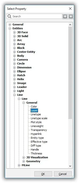
Properties
Close the Properties dialog box by clicking OK. Notice that "Layer" is added under Group.
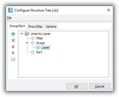
Entities grouped by layer
Let's see what this has done to the Stricture panel. Click OK to close the dialog box. Notice that the panel lists the "Lines by Layer" rule.
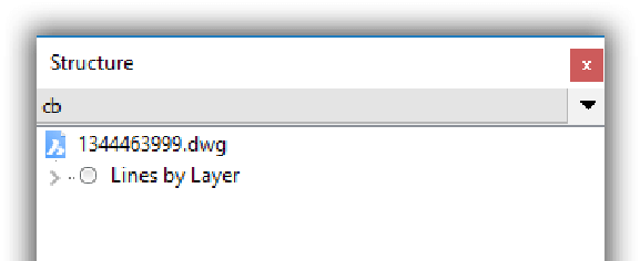
New rule displayed in Structure panel
Now let's see what is listed under that rule. Click the > next to "Lines by Layer."
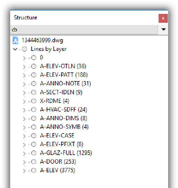
Layer names in the drawing
So far it looks good. You see the list of all layer names in the drawing. The number in parentheses next to each layer name is the number of entities on that layer, such as (36) for A-ELEV-OTLN.
Click the > next to layer "A-ELEV-OTLN." Oops! What's this? The icon shows that those are polylines listed.
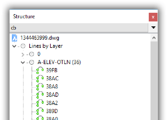
Polylines listed by layer
To restrict the list of entities to lines only, follow these steps:
Return to the Configure Structure Tree dialog box by clicking the "cb" bar.
Click the Show/Skip tab.
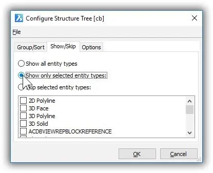
Restricting the entities listed by Structure
Choose the radio button next to Show Only Selected Entity Types.
Scroll down until you find Line, and then click the box next to it.
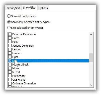
Choosing the Line entity
Click OK to dismiss the dialog box.
Now open the "Line by Layer" rule in the Structure panel. Notice that fewer layers are displayed, because now only layers with lines are listed.
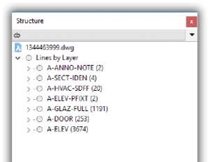
Only layers with lines listed
Open a layer name. Notice that just line entities are listed.
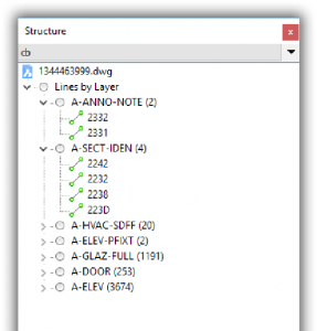
Lines on each layer
Add a subcategory, such as the length of each line. Follow these steps:
Return to the Configure Structure Tree dialog box by clicking the "cb" bar.
Right-click Group and then choose Add Grouping Property from the shortcut menu.
In the Select Properties dialog box, navigate to Entities > Line > Line > Geometry > Length.
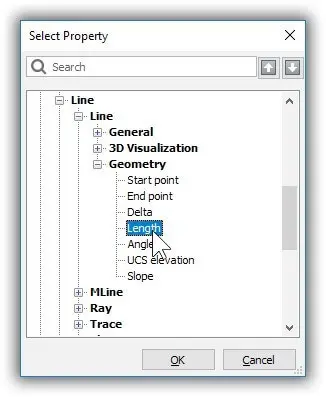
Adding Length to the group
Click OK. Notice that Length is added under Group.
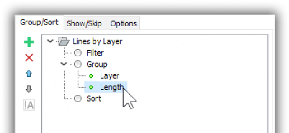
Length added to the Group section
Click OK to close the dialog box. Open up the nodes to find that the layers and lengths of lines are listed, such as layer "A-ANNO-NOTE" and then 3'0".
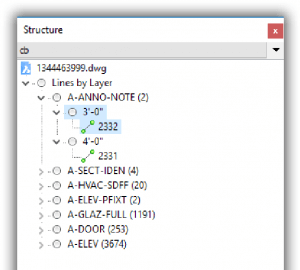
Lines listed by layer name, and then by length
Let's now sort the elements alphabetically. Follow these steps:
Return to the Configure Structure Tree dialog box by clicking the "cb" bar.
Right-click Sort and then choose Add Sorting Property from the shortcut menu.
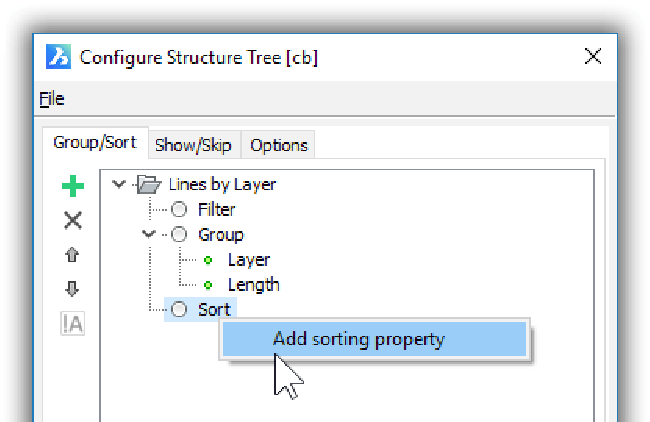
Adding a sorting property
Choose Entity Type and then click OK twice to dismiss the dialog boxes.
Take a look at how the added rule affected the listing: notice that the layer names are now alphabetical.
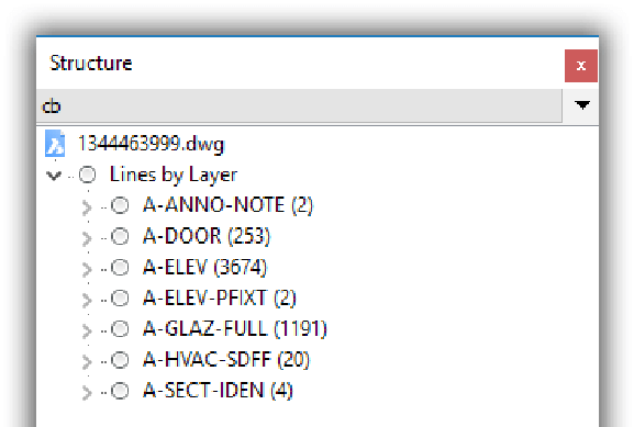
Layer names listed alphabetically
As a final step in this tutorial, let's switch the order of the Layer and Length rules, like this.
Return to the Configure Structure Tree dialog box by clicking the "cb" bar.
Select "Length" and then click the up arrow button to move it above the "Layer" rule.
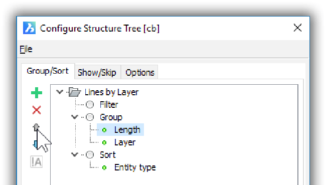
Changing the order of rules
Click OK to dismiss the dialog box.
Notice that lines are now listed by length and then by layer name.
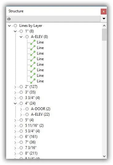
Lines listed by length and layer
Show/Skip Tab
The Show/Skip tab gives you options on how to display items. This lets you filter out entities you are not interested in seeing in the Structure panel, such as ordinary lines.
Show all entity types in the drawing (default)
Show only selected entities types chosen in the list below (those with the checkmark) Skip selected entity types as chosen in the list below
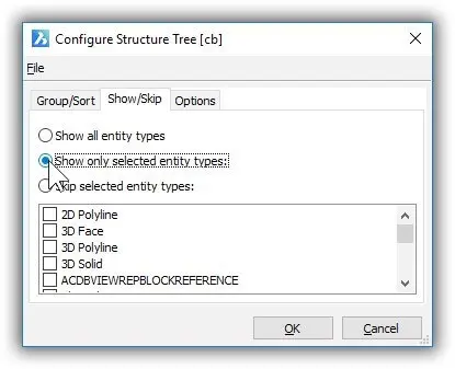
Options found in the Show/Skip tab
Options Tab
The Options tab provides options that control what happens with the structure tree:
- Ignore tree selection --- nothing happens when you select an item in the Structure panel
- Highlight entities when selected in tree --- (default) when you select an item in the Structure panel, it gets highlighted in the drawing
- Select entities when selected in tree --- when you select an item in the panel, it is also selected in the drawing, following which you can immediately edit it
On entity selection, select in tree --- when on, the entity you select in the drawing is highlighted in the Structure panel
On entity deselection, collapse in tree --- when on, the tree in the Structure panel collapses when the entity is no longer selected in the drawing . This is useful, because the content in the panel can get very long.

Specifying options
Add nested blocks --- when on, includes blocks that are nested inside other blocks.
Explode external references in tree --- when on, lists all elements in an xref separately; when off, lists the xref as a single element.
Download BricsCAD free for 30-days
Start Using BricsCAD Today
Permanent or subscription licenses that work in all languages, in all regions.
- Introduction
- 55 Tips for BricsCAD Users
- Settings
- Changing the Environment
- Custom User Interface
- Introduction to the Customize Dialog Box
- Customize the Menu Bar & Context Menus
- Toolbars and Button Icons
- Writing Macros and Diesel Code
- Ribbon Tabs and Panels
- Keystroke Shortcuts, Aliases & Shell Commands
- Mouse, Double-click & Tablet Buttons
- Absolutely Everything You Need to Know About The Quad
- Rollover Properties
- Workspaces and the User Interface
- Designing Tool & Structure Panels
- Creating Simple & Complex Linetypes
- Patterning Hatches
- Decoding Shapes & Fonts
- Coding with Field Text
- Writing Scripts
- Programming with LISP (Introduction)
- LISP Functions

