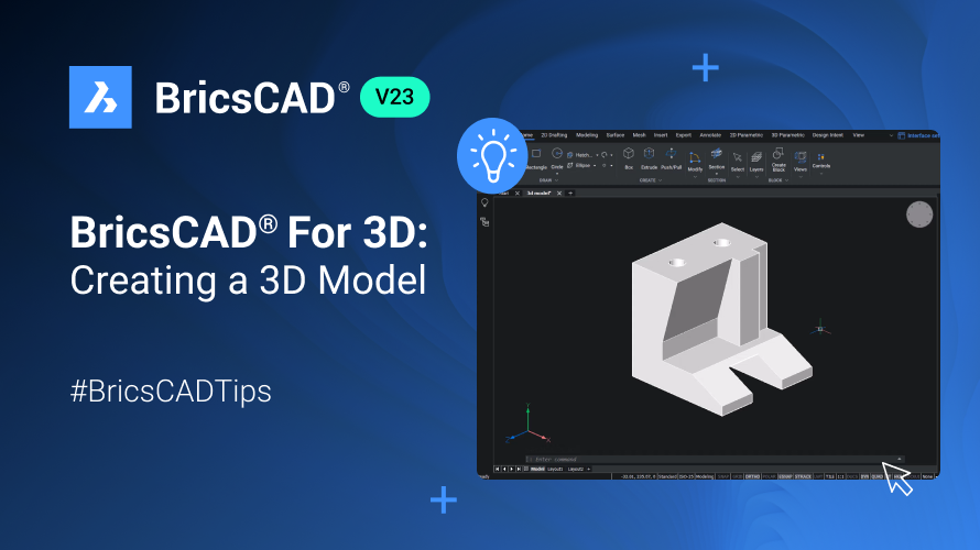
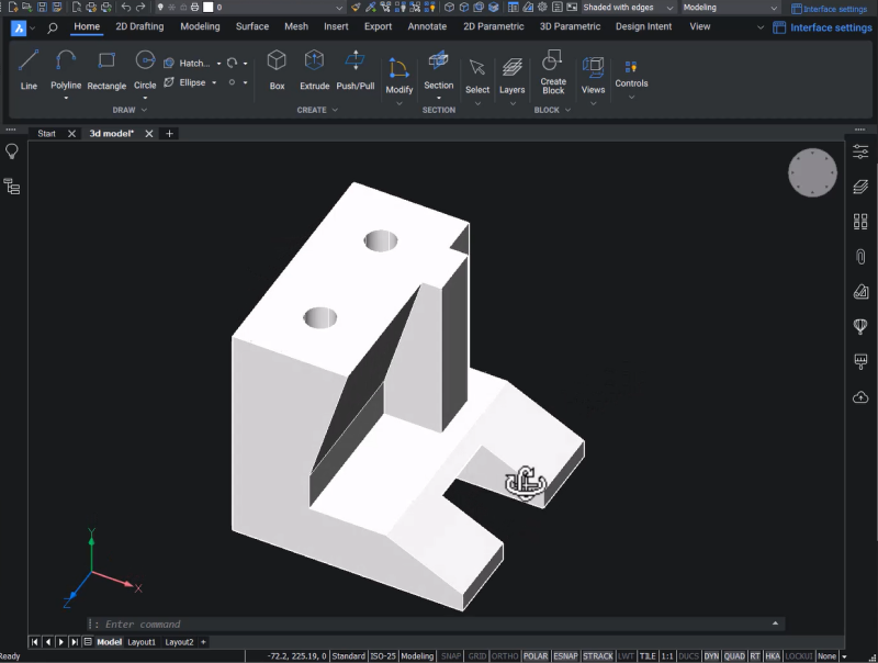
You can create 3D models in BricsCAD® quickly and easily using BricsCAD's familiar tools and 3D workflows. Let's take a look at how you can create 3D models in BricsCAD and get acquainted with some simple modeling tools and UCS applications - starting with this straightforward mechanical component!
How to create a 3D solid in BricsCAD®
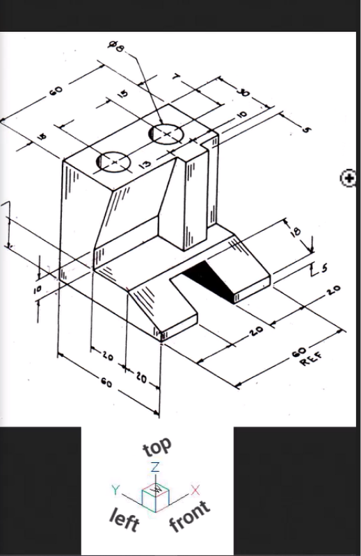
First, you need to create the object's profile. From the reference figure, you can see that this object is facing the left.
- Change the view to Top Front Left to match the view of the model in the drawing by clicking on the Top Front Left face in the Look From widget.
- To align the UCS to the left face, click on the View tab, then click the Coordinates button to open the flyout.
- Click on UCS to open the User Coordinate System dialogue.
- Click on left to align the UCS with the left face.
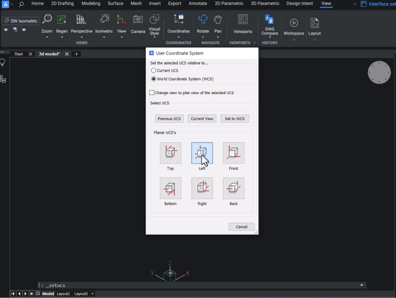
Next, let's create a few construction lines to complete the profile, taking all the dimensions from our reference figure.
- Click the Line button or use the LINE command and pick a starting point.
- Keep ortho mode on, drag the cursor straight down, and set the value to 60.
- Drag the cursor to the right and set the value to 60.
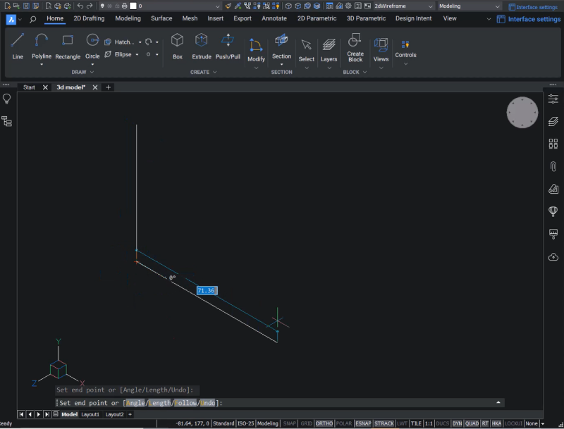
Now that you have constructed two lines, you must create several offsets using the OFFSET command.
- Create two offsets and set the distance to 20.
- Create one with a distance of 30.
- Create one with a distance of 5.
- Create one with a distance of 15.
- Create one final offset with a distance of 10.
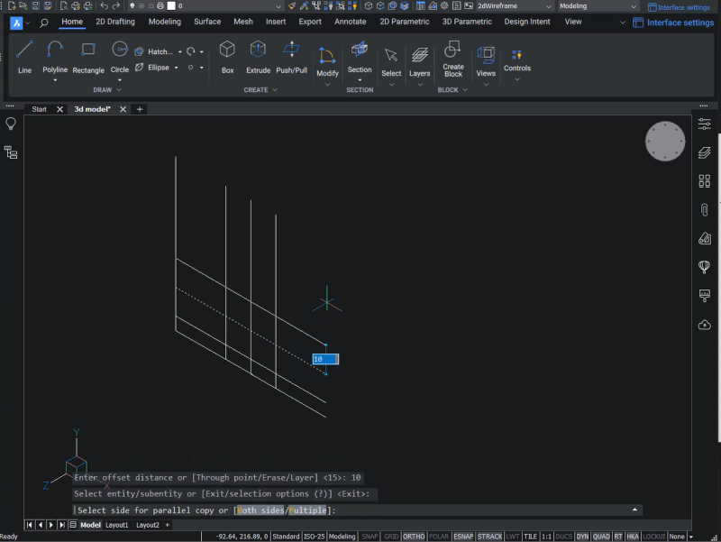
Now to create a 3D profile, use the polyline command.
- Use the Polyline button or enter the PLINE command
- Connect all the necessary endpoints to complete the polyline profile.
- Click on Close to close the polyline.
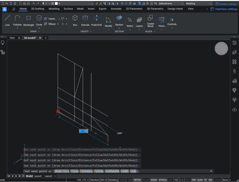
You've now created the profile. Next, navigate to the profile with your cursor and see the Quad menu appear.
- Hover your cursor over Model and click on Extrude.
- Keep the cursor in the -Z-axis direction and set the distance to 60.
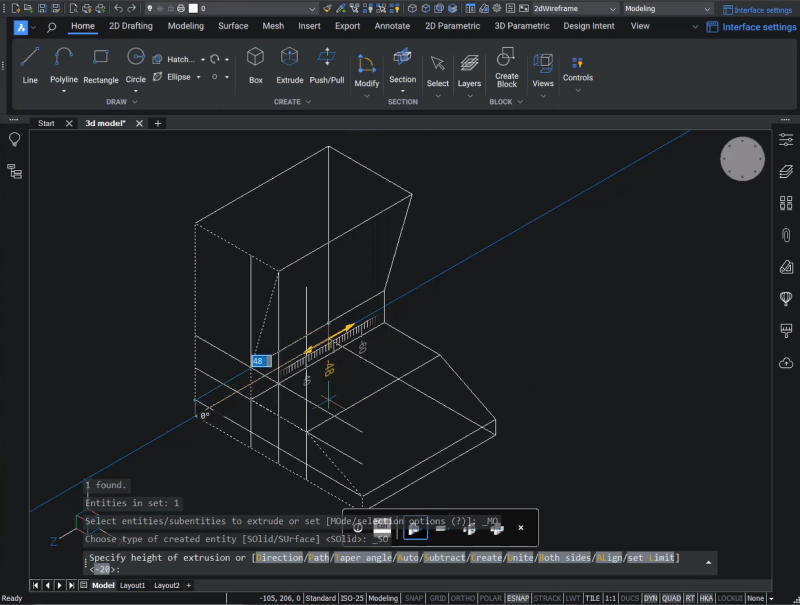
- Now that you've extruded the profile, you no longer need the construction lines – delete them using the ERASE command.
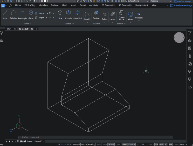
To create the component at the front of the model, create the profile and use the EXTRUDE command.
- Use the polyline (PLINE) command, and starting from the top of the drawing, set the distance of the polyline to 5 in the direction of the X-axis.
- Drag the line straight down to the desired point.
- Hit the Shift button, right-click, and choose a perpendicular point.
- Connect these endpoints and close the polyline.
- Select the polyline and extrude it using the extrude option in the Quad menu. In this example, we've input 13 as the extrusion height in the -Z-axis direction.
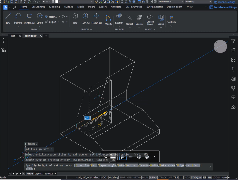
- Move this component in the -Z-axis direction to your desired location.
- Select the component, click on Move in the Quad, and pick this point as a base point.
- Keep the cursor in the -Z axis direction and set the distance to 37.
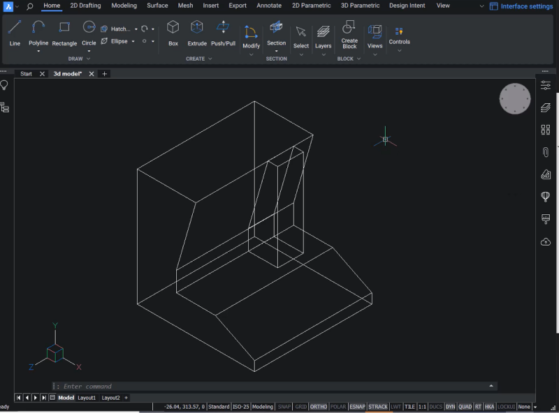
As you can see in the reference figure, you need to add a flattened element. Again, start by creating a profile using polylines.
- Create a polyline coming straight down to connect the endpoints.
- Close the polyline and extrude it using the Extrude option in the Quad, setting the extrusion height to 10.
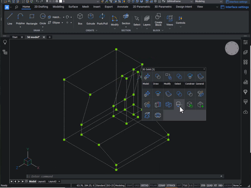
You can see that you now have three components that must be combined using the UNION command.
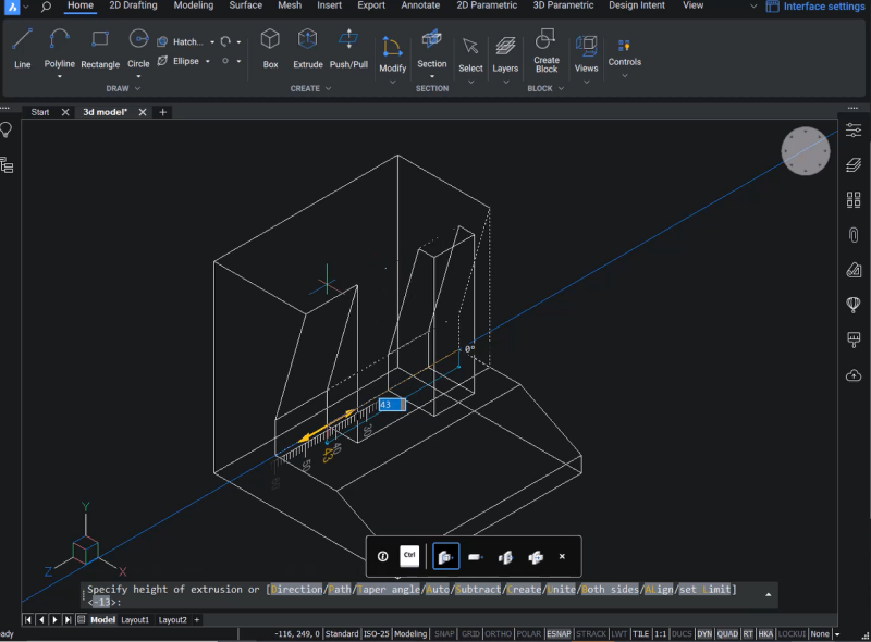
- Select the components.
- Select Union from the Model tab in the Quad.
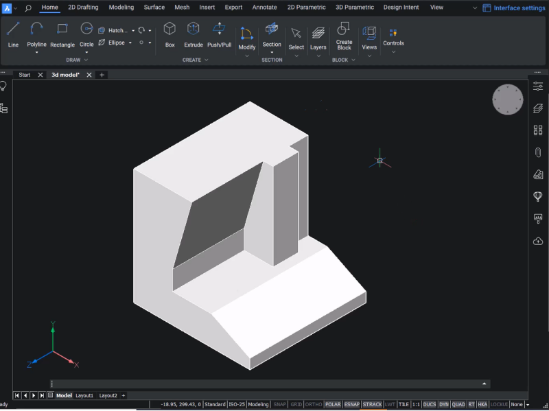
- Change the visual style to Shaded with edges; now you can see that you have combined these components into a single unit.
Next, we will create the two holes on the top of the model.
- First, align the UCS on the top face.
- Ensure that the Dynamic UCS is turned off. If it is on, the UCS will automatically align with this face.
- To view the UCS command options, click on the View tab and then on Coordinates.
- Select the 3 point UCS command option. This option lets you define a new UCS by choosing three points.
- Choose the origin point, a point on the +X axis, and a point on the +Y axis.
Now you have a new UCS!
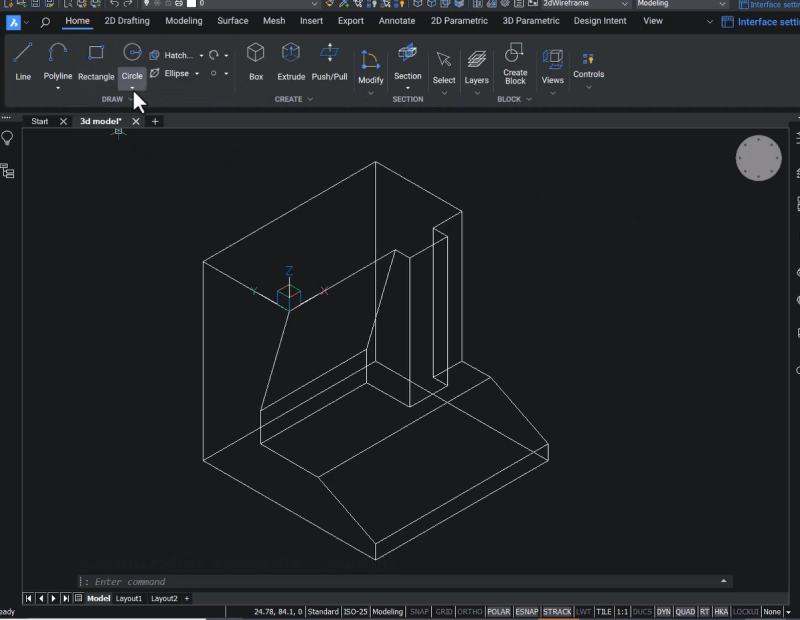
Next, use the CIRCLE command to create the holes.
- Choose the Circle Center-Radius option and define the center point using the absolute coordinates – in this case, 15,15.
- Since the diameter of the circles in the figure is 8, the radius of the circle you create will be 4.
- Extrude the circle, take it straight down, and set the extrusion height to 60.
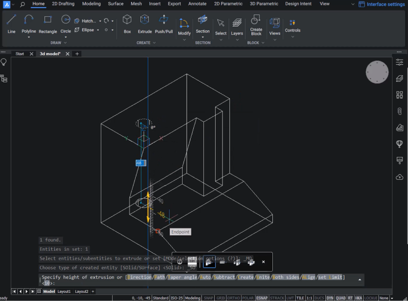
- Copy the extruded circle in the +X axis direction, setting the distance to 30.
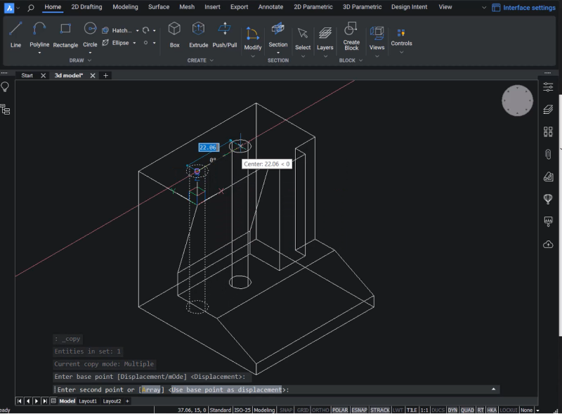
You can see in the figure that there is a slot at the front of it. To create this, align the UCS on the slanted face.
- To align the UCS on the selected face, click on the View tab, the Coordinates button, and click on the UCS face.
- Hit Enter to accept the orientation of the UCS.
- Next, draw a line upwards from the midpoint on the bottom line and set the distance to 18.
- The figure indicates the slot's width is 20, so move the line to a distance of 10, i.e., half the width of the slot.
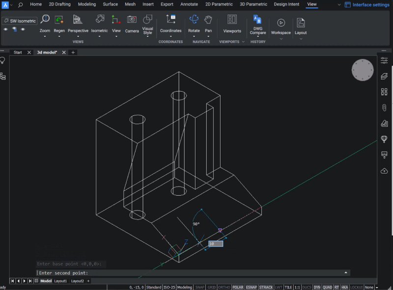
Now, you need to change the UCS to its original configuration.
- Click on the Coordinates button in the View tab, and click on UCS Previous in the flyout. Repeat this step.
Now, the UCS is back to the original configuration.
- Next, create a polyline starting from the endpoint of the slot and take it straight over to the back left corner.
- Drag the polyline back to the original point and close the polyline.
- Now, extrude this profile and set the height to 20.
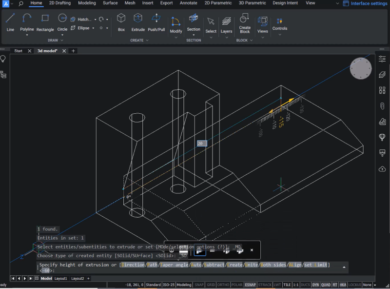
Then, you must subtract the circles and the solid you used to create the slot from the main solid.
- Select the main solid.
- Hover over the model tab.
- Select Subtract, then select the extruded circles and the slot and hit Enter.
- Change the visual style to Shaded with Edges for a final touch, and you have a complete 3D model!
Do you want to create 3D models in BricsCAD?
Download the 30\-day free trial now and start exploring how you can start modeling in BricsCAD.
Have you used BricsCAD for 3D and have some ideas or suggestions?
Fantastic! We love hearing your thoughts on BricsCAD® – all feedback is welcome, whether good or bad. The best way to tell us what you think about BricsCAD is to send us a support request; our support team will gladly help.
Wilt u meer BricsCAD-tips en trucs?
If you're curious about what else you can do in BricsCAD, check out our YouTube channel to learn more about BricsCAD's features and commands, or take a peek at the rest of the Bricsys blog.
