BricsCAD® Mechanical V24 provides manufacturers of all sizes with the fastest path to complete and accurate production materials. With this release, we've focused on helping our users with cost-saving and software deployment. We have bridged functionality gaps between BricsCAD Mechanical and other CAD software, so now it's simpler to make the switch to BricsCAD, save on cost, and accelerate your time to deliverable.
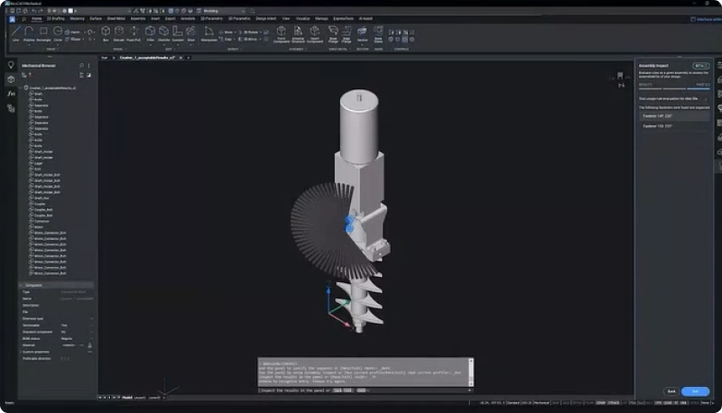
We developed BricsCAD Mechanical V24 with our users' needs in mind, so we included highly requested features to bring you a complete designing and drafting toolset that is familiar and compatible with your current software. Let's look at what's new in BricsCAD Mechanical V24!
Workflow compatibility with Part Reference and Associative Part Lists
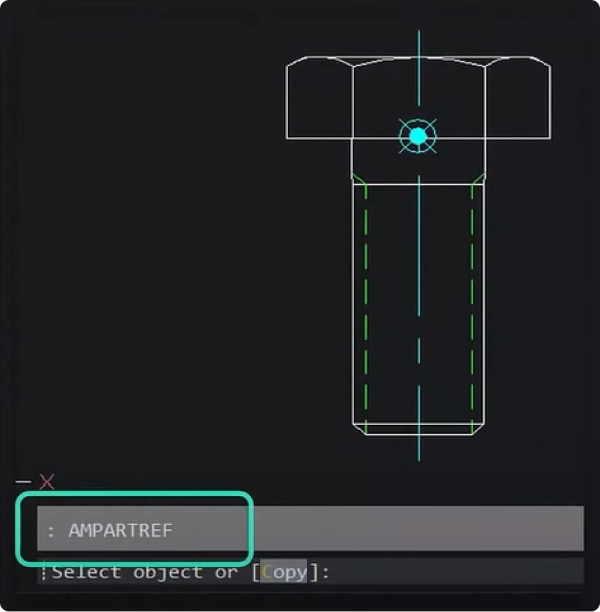
We've made interoperability even more seamless, so using your legacy DWG files with BricsCAD Mechanical is easier than ever. When you migrate from your legacy CAD to BricsCAD, you can rest assured that you can work with the DWG files you created in your previous software with no loss of vital part reference or part list data. If you need to make a new part reference, you can do so with the AMPARTREF command and add properties to the part reference via the Properties Panel. Add the part name and number, and you'll be able to see it appear in the part list.
BricsCAD® Mechanical's 2D design and drafting capabilities
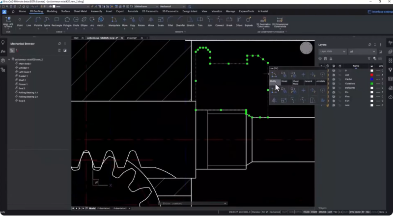
The powerful 2D design capabilities in BricsCAD Mechanical V24 let you quickly update existing drawings. You can quickly turn drawings into mechanical components with the BMFORM command. This command creates a new mechanical component as an internal reference in your current drawing.
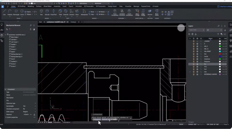
You can further optimize the drawing process with intelligent commands like CopyGuided, automatically aligning copied entities with relevant geometry using temporary guide curves and accepting polyline and multi-line segments with guide lines.
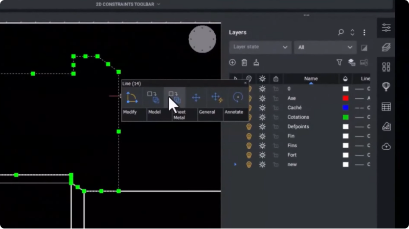
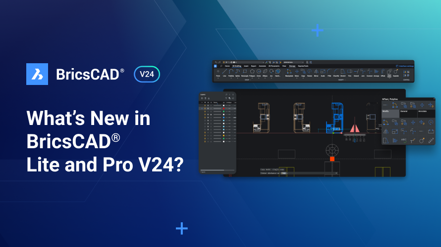
Unique BricsCAD features like the Quad speed up your CAD workflow by directly displaying your most used and needed commands under your cursor.
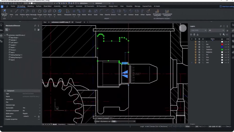
The Manipulator is a visual tool that gives users dynamic movement, rotation, mirroring, and scaling of selected geometry without command input, helping you save time and ensure accuracy.
Turn 3D assembly models into 2D drawings with BricsCAD® Mechanical
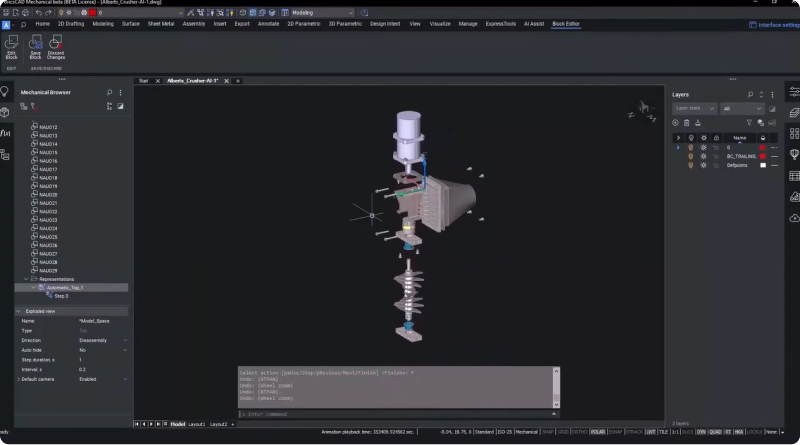
BricsCAD Mechanical V24 helps designers convert 3D models into complete and accurate production materials. Assembly technicians need a package of materials to complete their job effectively, and creating these materials requires various personnel, from engineers to illustrators. Using BricsCAD Mechanical ensures you can generate these materials all in one single platform.
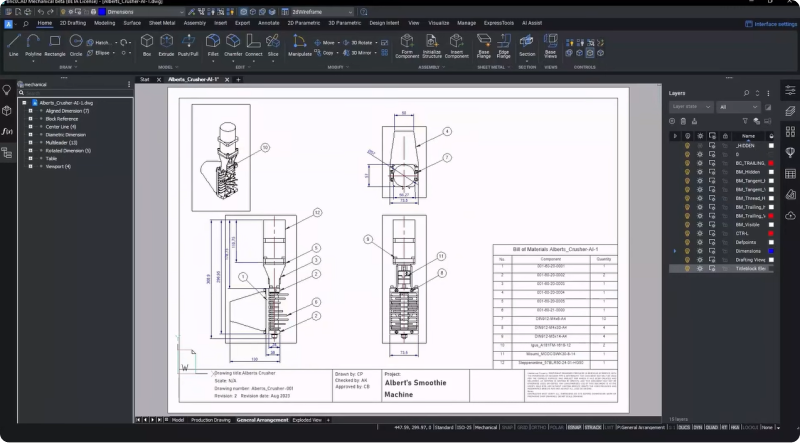
When you need to turn your 3D assembly models into drawings to pass on to the production team, you can generate component production drawings to allow the assembly technician to reference the drawing against the actual component to check for any deviation from the manufacturer's specifications.

Once you've generated the component production drawing, you can visualize the final product with a general arrangement drawing. This drawing includes details like high-level dimensions, component locations in the assembly, and a parts list or BOM for the assembly with annotations.
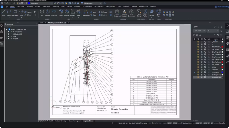
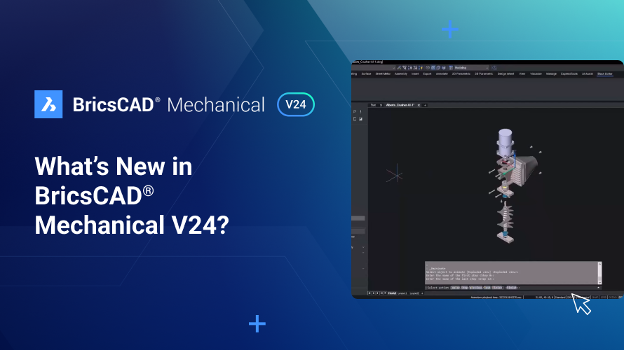
The exploded view drawing of the assembly gives you a high-level overview of how the various components come together. These drawings include trailing lines indicating how the components interact to create the final product.
Create 2D instruction manuals from 3D assemblies with annotations
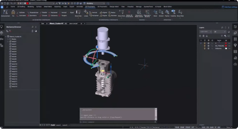
You can generate an assembly manual for a detailed, sequential, step-by-step product assembly guide. The manual includes detailed instructions outlining when and how the components should be assembled. Each step will have assembly notes and a pictorial graphic generated from your CAD model.
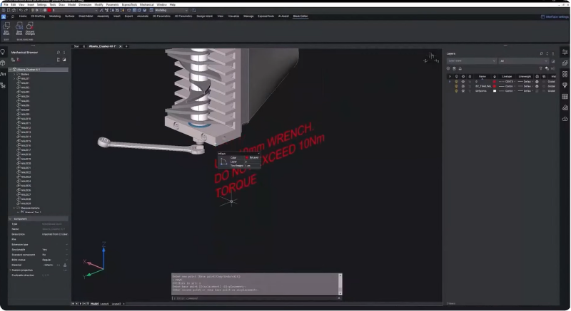
BricsCAD Mechanical can help you quickly and easily create 2D instruction materials from your 3D models for assembly production. You can add particular details to each step in the assembly process on the 3D model. BricsCAD lets you communicate plenty of detail in each step of the process. Insert 3D annotations like arrows, tools, or text into the 3D model space, then select which steps you want to add it to, and the annotation will only appear on those steps.
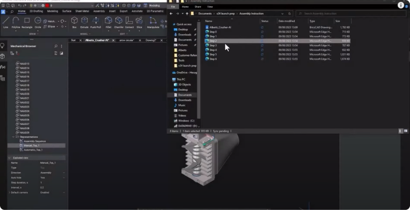
Then, you can export the step sequence to an SVG file complete with annotations. Each step in the sequence will have its own SVG file. You can then import the SVG for the relevant step in the manual.
Optimize DFMA with existing 3D models with BricsCAD® Mechanical's assembly inspection and validation tools
When you create your manual, you'll want to ensure that the instructions produced are the best option for your assembly or maintenance process. In BricsCAD Mechanical V24, we've provided a prototype of our growing manufacturing validation or design for manufacturing and assembly toolset. Now, you can set up analysis rules and ask BricsCAD to inspect the assembly steps and ensure your assembly instructions are as efficient as possible.
To use the assembly inspection tool, you need an as-built sequence to start the assembly validation process. This sequence mirrors the order in which the technician would assemble the components in the real world. You can also use this sequence to create assembly instructions.
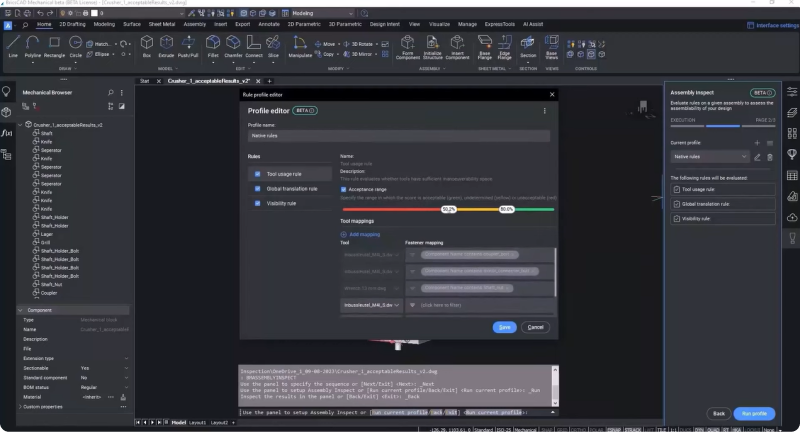
The Assembly Inspect command starts the inspection tool process. In the inspection dialog, you can select the newly created as-built sequence and verify that its steps match the order in which it should be built. You can choose a 3D model of the tool required in the assembly process from the configuration tab and map this to the components it's used on.
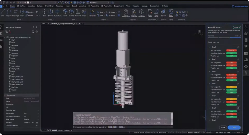
The next step allows you to check the rules and parameters used on the assembly you're configuring. You can configure three parameters: tool usage, global translatability, and visibility. Once you set these parameters, you can run the validation process and view the results, which show an evaluation of each set of rules for each step so you can easily see any changes you need to make.
BricsCAD Mechanical makes it easy for non-3D experts to reuse existing 3D models easily for technical publications and design for manufacturability studies, and now users can generate a component drawing, a general arrangement drawing, an exploded view drawing, and graphics for an assembly manual - all in one platform!
There's plenty more in BricsCAD Mechanical V24, so watch our Breakout Sessions for an in-depth look at some of these new features!
Want to learn more about BricsCAD® V24?
If you're curious about what else you can do in BricsCAD V24, check out our YouTube channel or take a peek at the rest of the Bricsys blog to learn more!
Have you used BricsCAD® V24 and have some ideas or suggestions?
Fantastic! We love hearing your thoughts on BricsCAD® – all feedback is welcome, whether good or bad. The best way to tell us what you think about BricsCAD is to send us a support request; our support team will gladly help.
Get started with BricsCAD® V24 today!
Buy BricsCAD or download the 30-day free trial now and discover how you can accelerate your time to deliverable with BricsCAD.
