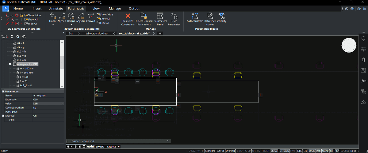
This project will show you how to create parametric table and chairs blocks, with visibility states. This tutorial is split into two parts: a circular table and a rectangular table. These are practical projects, designed to help get you started with 2D parametric drawing, nested blocks and visibility states in BricsCAD. The last post showed you how to create a circular table. In this post, learn how to create a parametric rectangular table and chairs arrangement, with variable spacing between the chairs.
This project will cover:
- How to add constraints to a 2D drawing
- How to create and edit the value of parameters
- Simple animation of constraints and parameters
- Working with visability states
- How to use a design sheet (Excel, Google Docs or similar) to create design variations
Before we begin...
- If you need to manually enter a value during the exercise, it will be shown in green.
- All dimensions are shown in mm however you can use any unit you like.
- 2D Geometric Constraints and 2D Dimensional Constraints are located in The Parametric tab of The Ribbon.

- You must have an understanding of how to draw basic shapes in BricsCAD. If you are not yet familiar, please see our Beginner CAD Course.
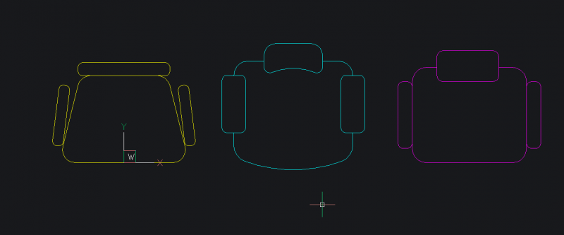
- These are the chair blocks used for this project.
Quick guide to terminology:
- **Parameter** -- defines the position, distance, and angle of geometry
- **Constraint** -- a rule: position, slope, tangency, dimension, and relationship of geometry
- Expression -- formula or absolute value of a parameter or constraint
Tutorial: Create a rectangular, parametric table and chair set with visibility states
Time to complete: 60 mins
Difficulty: 6/10 
Create a rectangular table and chairs:
Draw a rectangle 80 x 250. This will be the table.

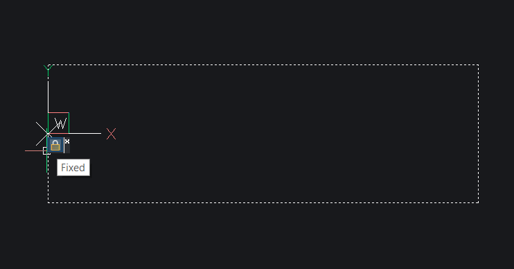
Add a Fix Constraint to the left side of the table.
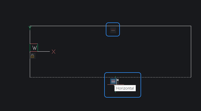
Add Horizontal Constraints to the top and bottom edges of the table.
Add Vertical Constraints to the left and right side of the table.
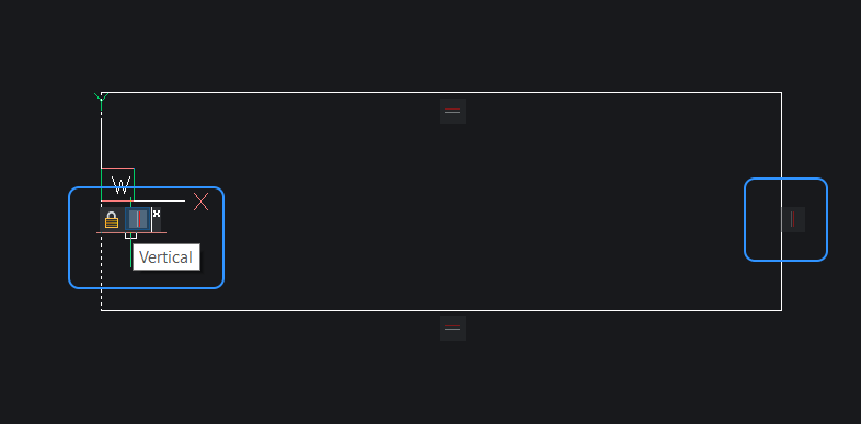
Add a Linear Constraint to the left side of the table.

Add a Linear Constraint to the length of the table.
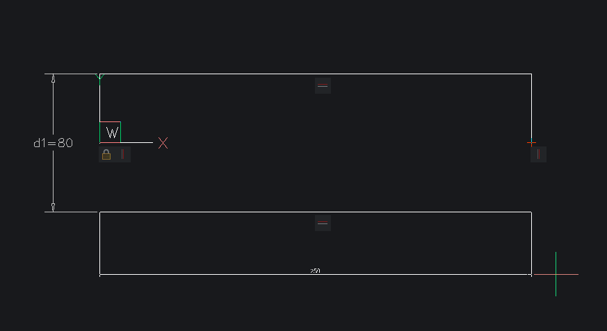
In the Mechanical Browser, click on the parameters and change the names of the parameters:
(old) Name: d1
(new) Name: w
(width of table)(old) Name: d2
(new) Name: l
(length of table)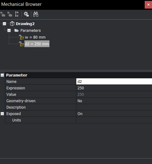
In the Mechanical Browser, add four new parameters. Right click Parameters and choose Add New Parameter from the drop down menu.
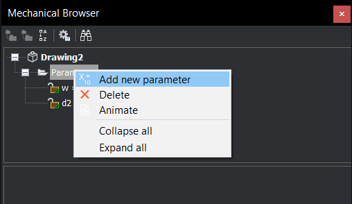
In the Mechanical Browser, click on the new parameter and change the value of the parameter in the bottom of the panel:
Name: s
Expression: 50
(For the gap between chairs)Name: c
Expression: l/s
(for the number of chairs)Name: g
Expression: 10
(for the gap between the table and the chair)Name: h
Expression: 25
(for the gap between the edge of the table and the middle of the chair)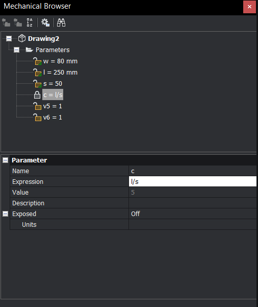
Insert a chair, as a block 25 x 10 from the top left corner of the table.
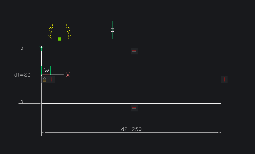
Tip: I created chairs as blocks with a base point at the middle of the line that marks the boundary of the chair cushion.Use ARRAYRECT on the chair.
Set the Base Point as the middle of the line that marks the boundary of the chair cushion (the same as the block base point).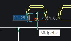
Number of Rows: 0
Number of Columns: 5,
Distance Between Columns: 50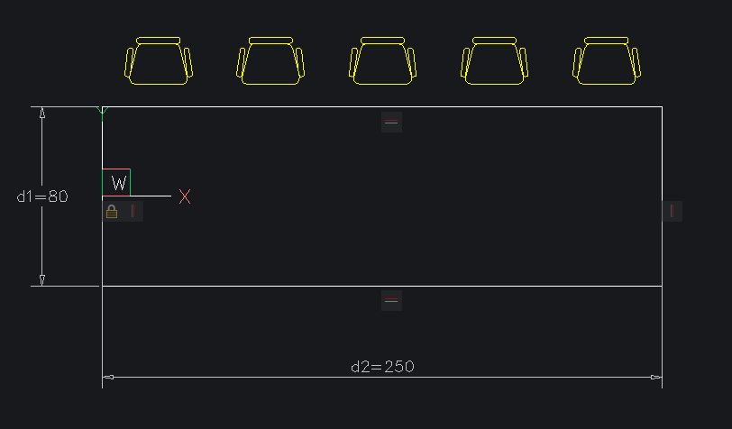
Mirror the Array.
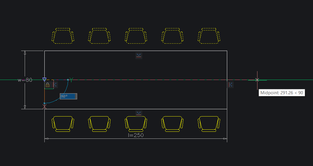
Add a linear constraint between the top of the table and the base point of the top array.
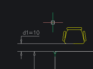
Add a linear constraint between the side of the table and the base point of the top array.
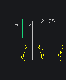
Repeat steps 10-11 on the bottom array.
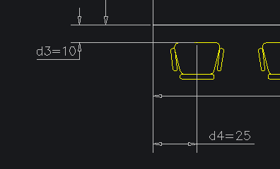
In the Mechanical Browser, click on the parameters and change the value of the parameters in the bottom of the panel:
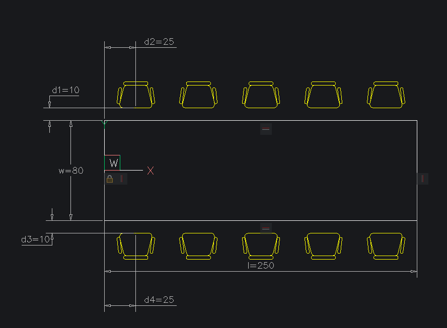
Name: d1
Expression: gName: d2
Expression: hName: d3
Expression: gName: d4
Expression: h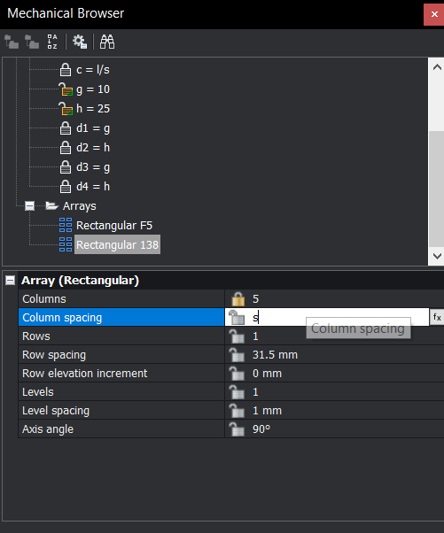
WARNING: The names of the parameters may vary. Use this image as a guide:
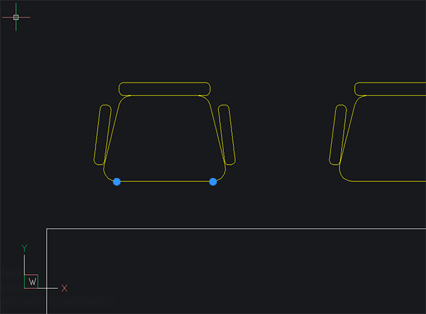
Add Horizontal constraints to the Arrays, use the 2Points option. (See image for location of the two points.)
In the Mechanical Browser, click on the arrays and edit the value at the bottom of the panel:
Columns: c
Column spacing: s
In the Mechanical Browser, right-click on the parameters and select Animate from the drop down menu to see how everything is working. You should now have something like this:

Repeat steps 10-19, for the other chair styles.
Note: The name of the linear constraints will change for each subsequent chair style. Pay attention to this.
Tip: It's useful to hide the arrays before you add a new chair style.
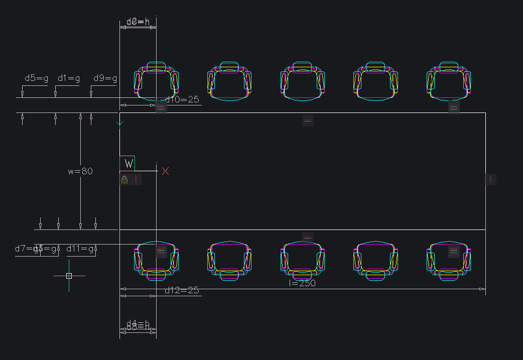
Once you have completed this step you should have something that looks like this. It looks a bit messy at the moment, but don't worry!
21. Enter VISIBILITYSTATES. A dialog box will display.
22. Click New Parameter and give it a name.
23. Right-click the Parameter and select Add State.
24. Repeat step 23, two more times.
25. Name the visibility states: Economy, Mid and Premium.
26. Select one of the visibility states.
27. Right-click and use the Select invisible entities/Select visible entities options to hide and show the table and correct chair arrays for each state.
28. Select the next visibility state.
29. Rick-click and select Show invisible.
- Repeat steps 26-28 for the remaining visibility states.
- Rick-click and uncheck Show invisible. This will hide entities based on the visibility state.
- You should now have something like this:
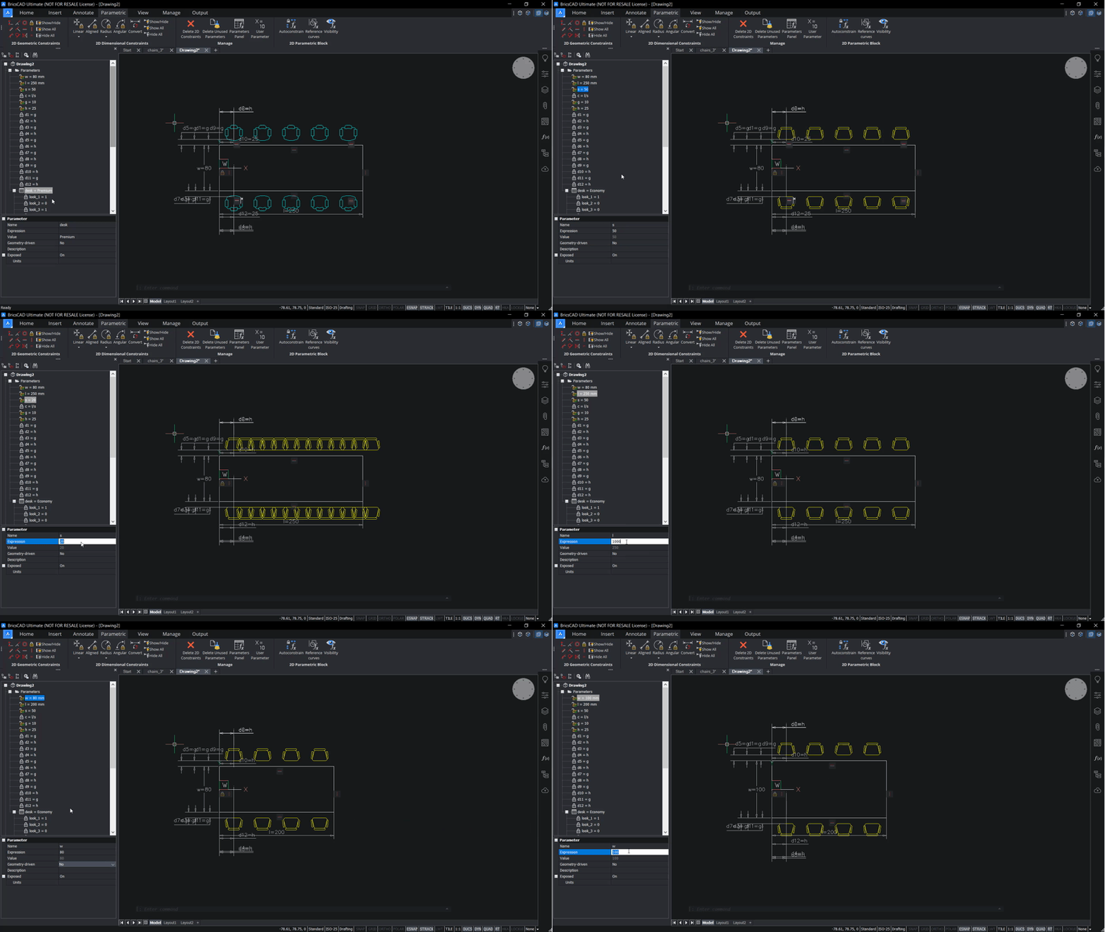
Tip: If you wish, you can create a design table for this project.
Happy CADing!
Download BricsCAD free for 30-days
Get started using 2D parametric blocks in BricsCAD
Permanent or subscription licenses that work in all languages, in all regions.
Enjoy this project?
Why not try some other easy builds?
