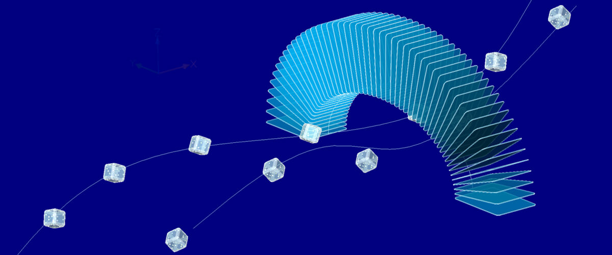
Arrays can be super useful for creating copies. BricsCAD V19 brings you the option to array objects along a path. Copy blocks, shapes, lines and solids along 2D and 3D, open and closed, splines and polylines. Automatically create chains, links and banister spokes.
The basics
Array path is a super useful tool when duplicating objects. Whilst array polar and array rectangle have their merits, array path is a whole new level of CAD.
Start by selecting the item you want to array and placing it at the end of a given path (vertex 1).
To find a vertex select the path, then use the Properties panel. If you click in the box labeled vertex then you can navigate along the path, a small cross will be displayed at the vertex in question.

Use the properties panel to find the first vertex. The vertex indicated in the panel will be highlighted with a small cross.
Then move the object to this point. For best results align the vertex to the center of the object. Use entity snaps to get it precise.
Then align the object along the path. You can either use the ALIGN command or eyeball it.

Screen capture from BricsCAD
Set the number of items along a given path using dived or the distance between items using distance. You also have the option to fill the whole path, or just a set the number of items.
More options
You can choose to align items along the path or not. When aligned the object will rotate with the bend in a curve or when off it will remain at a uniform angle.

If no alignment is set, the results will be like this.
If you don't follow this step you might get some crazy results. To fix that you can use base point followed by Tangent direction.

Left: Object placed on point of the line other than vertice 1. Right: Basepoint and tangency adjusted. The object has not moved.
Tangent direction affects the alignment of an object along a path.

The white arrow illustrates the direction of the set tangency. Top left: no tangency set.
More options
You can also add rows and columns to the object, much as you can with ARRAYRECTANGLE and ARRAYPOLAR.

ARRAYPATH levels were used to create this simple sheet of chainmail.
It also works on helix curves, which allows you to create objects like spiral staircases quickly and easily.

Quickly draft a spiral staircase using ArrayPath
You can choose between the modes: Distance and Dived (numer of items along a path).
If you selected create associative array, once you've created an array you can edit the path as you would normally. The array will automatically update based on the edits. You can edit the number of rotations, and the height of a helix even after the array has been created.
Ready to try BricsCAD?
Easy to try, easy to buy, easy to own. That's BricsCAD. Download free for 30 days at www.bricsys.com. Freedom of choice, plus perpetual (permanent) product licenses that work with all languages, in all places. You'll love what we've built for you with the BricsCAD product family.

