In this post, you learn how to place fields in mtext, regular text, and in attributes, as well as how to customize the look of field text.
Fields are a special form of text that update automatically. Fields look like text with a gray background and show values provided by BricsCAD or the operating system, such as the diameter of a circle or the date and time. To show new values, the text can be updated manually or automatically.
For instance, the circle illustrated below at left has its area, center point, and so on described by regular text (white background) and by field text with the gray background. The gray background is only displayed and not plotted, and can be turned off with the FieldDisplay variable.
When the size of the circle is reduced and the field text updated, new values show up for the ones that changed --- the area, circumference, and radius. See figure to the right.

Left: Circle with field text in gray, and regular text.
Right: Changed circle with updated field text.
FIELD COMMANDS & VARIABLES
COMMANDS
Field --- displays the Field dialog box for constructing field text; also accessed through text commands such as MText and AttDef
UpdateField --- forces an update of field values, should they have changed
VARIABLES
DbMod (read-only) --- reports if the drawing has been modified by changes to fields
FieldDisplay --- toggles the gray background to field text
FieldEval --- specifies when fields should be updated; default = 31 (all turned on):
0 Not updated automatically
1 Updated when the drawing is opened
2 Updated when the drawing is saved
4 Updated when the drawing is plotted
8 Updated when the eTransmit command is used
16 Updated when the drawing is regeneration
NOTE The FieldEval variable does not update the Date field; it is updated only by the UpdateField command.
Placing Field Text
Field text is added to drawings through the Field, Text, MText, AttDef, and Table commands, and can be placed in dimensions and leaders (as mtext). Let's take a look at each one.
FIELD COMMAND
The Field command places field text in drawings in a manner similar to the Text command, placing single lines of text. It operates identically in Linux, Mac, and Windows. For this tutorial, the drawing's creation date is inserted as a field.
Enter the Field command.
: field
Notice that BricsCAD displays the Field dialog box.
Field dialog box
Select a field that you want by selecting a group (such as Date & Time or Document), choosing a field name from the group (like CreateDate or Author) and then applying formatting, if available.For this tutorial, the task is to insert the creation date as a field: CreationDate is in the Date & Time group. Follow these steps:
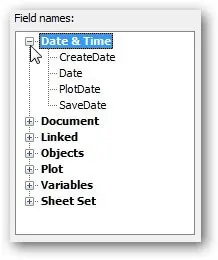
Under Field Names, open the Date & Time node by clicking the + button.
Fields available for Date & Time
Notice the fields that are available for specifying dates. Choose CreateDate.
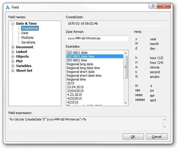
Notice that the empty part of the dialog box suddenly fills up with all kinds of options related to formatting dates and times.
Formatting options for the CreateDate field
You can format the date field by selecting a format from the Examples column or else construct your own format. For this tutorial, scroll down and then choose the one that looks like "Thursday, April 23, 2014." (The exact date displayed will differ.)

Selecting a format for the date
Notice that the Date Format area shows the date's format code: dddd, MMMM dd, yyyy. This is where you can edit the formatting code, something that I describe later.
Click OK. In the command panel, notice that BricsCAD prompts you with a set of Text-like options. (It shows "MTEXT"; it should say "TEXT.")
MTEXT Current text style: "Standard" Text height: 2.5
Pick a point in the drawing to place the field text:
Specify start point or [Height/Justify]: (Enter an option, or else pick a point)
BricsCAD places the field in the drawing with today's date, using the current text style. (The date you see will differ from the one shown below.)

Date generated by field code
If, however, the drawing is a new one and has not been saved, then all you'll see are four dashes, like this:

Field code that lacks meaning
This is the way that BricsCAD tells you a field lacks a valid value. To give the drawing a creation date, use the __Save__ command.
TIP When a field displays four hash marks, like #### , it means the field value is invalid for some reason.
FIELDS IN MTEXT
If you want to embed field text with regular text, then use the MText or AttDef commands; the Text
command and dimensioning commands can't do this. Embedding lets you mix regular text and field text in useful ways, such as the combination of "Date: " with a dynamic date.

Combining text with field code
In this tutorial, you place a field that reports the file name of the drawing.
- Start the MText command, and then answer its prompts:
: mtext
Multiline Text: First corner for block of text: (Pick a point)
Select Opposite corner for block of text or[Justification/Rotation angle/text Style/\ **text Height/Direction/Width]: (Pick another point)Type some text, such as "Drawing Name:".
To insert the field text, press Ctrl+F.
Alternatively, in the Text Formatting toolbar, click the Field button.
Or else right-click the Text Formatting toolbar, and then from the shortcut menu select Insert Field.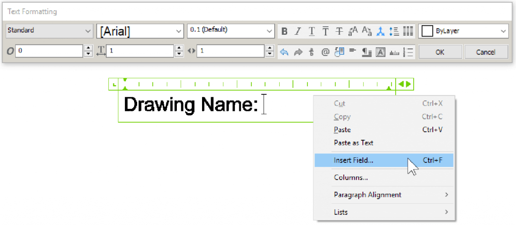
Accessing fields in the MText command
Notice that the Field dialog box opens. To choose the field for displaying the name of the drawing file, follow these steps:
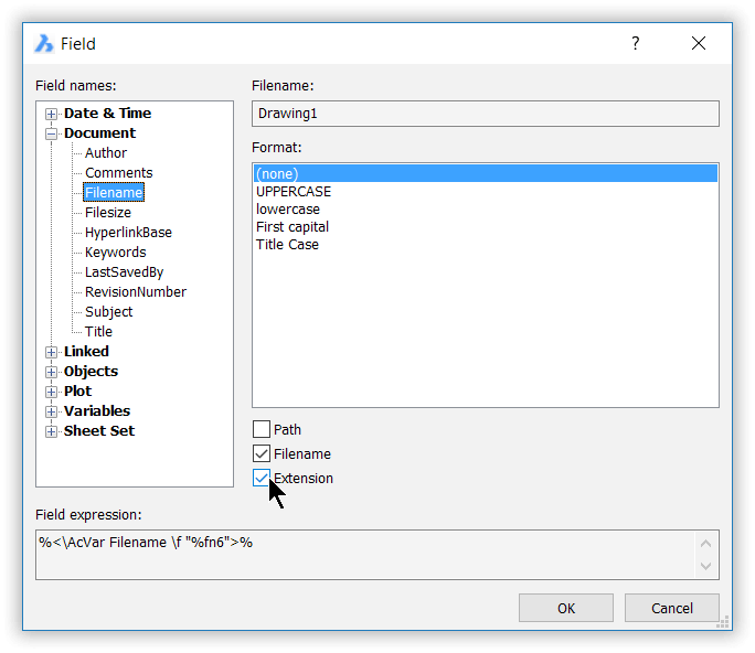
Choosing formatting options for the file name
In the Field Names list, open the Document node.
Under Document, choose Filename.
In the Format area, set these options:
Format (none)
Path No
Filename Yes
File extension Yes
Click OK. Notice that BricsCAD adds the file name field. It may appear as "Drawing1," or whatever the file name of your drawing is. You can tell that it is field text, because of the gray background.

Field text with filename
Exit the mtext editor by clicking OK.
To see field text in action, now save the drawing to change its name:
Enter the SaveAs command.
In the Save Drawing As dialog box, enter a file name like "Field text example."
Click Save.
Notice that the field text changes to reflect the new file name.
Field text with filename and exetension
FIELDS IN ATTRIBUTES
Field text can be made part of an attribute definition. Recall that attributes are used to add custom
data to blocks. As shown by the following tutorial, this is done with the AttDef command, which is
normally used to define attributes.
In this tutorial, you create an attribute that reports the current zoom level of the drawing.
Start the AttDef command. Notice the Attribute Definition dialog box.
In the Attribute section, fill in the attribute text fields --- Tag, Prompt, and Default fiels. YT; you can use the figure below as an example of the text to use:
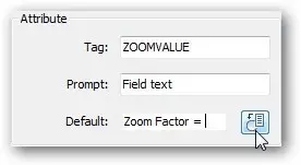
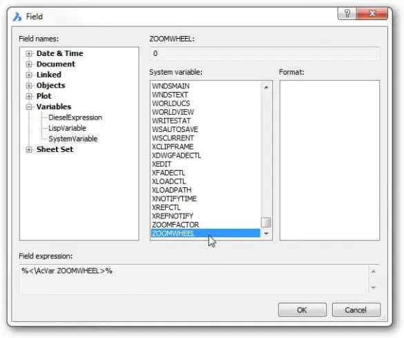
To add a field to the attribute, click the Insert Field button next to the Default field. Notice that BricsCAD displays the usual Field dialog box, as shown below.
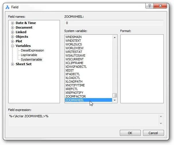
Field dialog box
Select a system variable like this:
From the Fields Name list, open the Variables node.
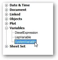
Choosing the SystemVariable field name
Select SystemVariable.
Under the list of System Variables, scroll right to the end and then pick ZoomFactor.
It has no format options, so click OK.
Click OK to close the Field dialog box.
Back in the Attribute Definition dialog box, notice that the field text shows in the Default box with a gray background.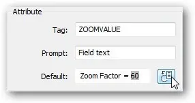
Entering field code as an attribute definition
Click OK to close the dialog box. All you see in the drawing is ZOOMVALUE.

No field text yet!
Start the Block command.
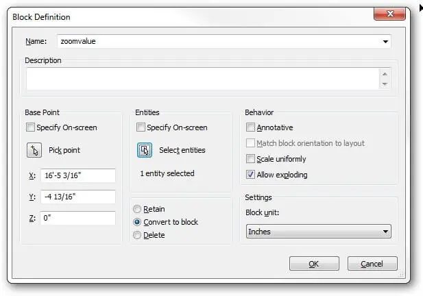
Placing a block as field text
Enter the following parameters:
Name zoomvalue
Base Point Click Pick Point, and then pick the lower right corner to ZOOMVALUE; use the INSertion point entity snap to assist you.
Using Insertion entity snap to locate the insertion point of the text
Entities Click Select Entities and then choose the text
Convert to Block YesTo see the field text, you need to turn the attribute into a block and then insert the block. Follow these steps:
TIP Users should not be allowed to modify fields, so turn on the Constant setting found in the Mode section in the AttDef dialog box.
- Click OK.
- When the Edit Attributes dialog box appears, click Cancel; you don't need its services.
- Zoom in and out. The zoom factor value does not change. To update the field takes two steps this time.
First, change the value of the zoom factor using the related varaiable:
: zoomfactor
New current value for ZOOMFACTOR (3 to 100) <60>: 5The field text still does not change (I'll explain later why this is), so enter the Regen command to see the value of the field updated.
: regen
Field text visible after Regen command
Changing Field Text
To change field text, simply double-click it; BricsCAD displays the Field dialog box. Use it to make
changes. Alternatively, you can change field values by using the Properties palette. Here, we look
at both approaches.
DOUBLE-CLICKING FIELDS IN MTEXT
To edit fields placed by the MText command, you use this procedure.
Double-click the field text. Notice that BricsCAD displays the mtext editor.
Click the field text. Notice that its background color changes to blue.

Field text in mtext
Now double-click the blue and notice that the Field dialog box appears. (Alternatively, you can right-click field text to access the following shortcut menu.)
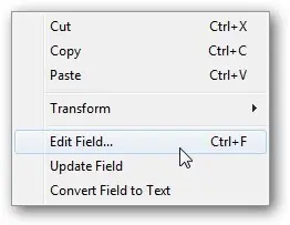
Accessing field text editor
Here's what the three field-related options mean on the shortcut menu:
Edit Field --- displays the Field dialog box.
Update Field --- forces an update the field's value.
Convert Field to Text --- turns the field into normal text, freezing the value of the field.Select a different field type, or change the field formatting.
Click OK to close the dialog box, and then click OK to exit the mtext editor.
So the background to field text changes color, depending on its editing state:
 Gray = field text in unedited state
 Blue = field text ready for editing
EDITING FIELDS IN ATTRIBUTE DEFINITIONS
When field text is in an attribute definition, you can edit it, as follows:
Double-click the attribute text. BricsCAD displays the Attribute Editor dialog box. (The EAttEdit command was executed.)
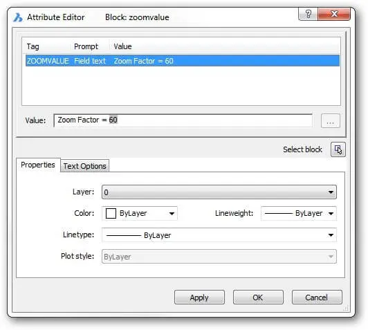
Field text in attribute editor
In the dialog box's Default field, double-click the gray field text. Alternatively, you can right-click the field text itself to access this shortcut menu:
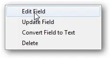
Accessing field text editor
Notice the Field dialog box. Make your changes and then click OK to exit the dialog boxes.
Controlling the Way Fields Update
The point to using field text is that it can update values --- manually or automatically. You force an update with the UpdateField command or else specify when automatic updates take place with the FieldEval system variable.
UPDATEFIELD COMMAND
To update selected fields manually, use the UpdateField command. It asks you to select one or more fields and then update their values.
: updatefield
Select field(s) to update: (Press Ctrl+A,or select individual fields)
Select field(s) to update: (Press Enter to end object selection)
*<n* field(s) found, *n* field(s) updated>
To update all fields in the drawing, press Ctrl+A at the 'Select fields' prompt.
FIELDEVAL COMMAND
Earlier, you used the Regen command to force the value of a field to update. This was an application of an automatic update that was dictated by the FieldEval sysvar. It wasn't the Regen command itself that did the updating; rather the command triggered BricsCAD to also update all fields in the drawing.
Fields are updated by BricsCAD when any of the following trigger events occur:
Open --- when the drawing file is opened
Save --- after the drawing file is saved, as you saw above with the CreateDate field
Plot --- before the drawing is plotted
eTransmit --- as the drawing is being prepared for packaging with the eTransmit command
Regen --- when the drawing is regenerated (reloaded from the .dwg file)
Note that the settings in FieldEval variable do not update Date fields; dates can be updated only
with the UpdateField command.
These events are controlled with the FieldEval system variable, which is best accessed through
the Settings dialog box:

Settings for field text
If you choose the access the system variable at the command line, it looks like this:
: fieldeval
New current value for FIELDEVAL (0 to 31) <31>: (Enter a number)
The value takes one or more of these values:
0 Fields are not updated automatically; use the UpdateField command
1 Open command
2 Save command
4 Plot command
8 eTransmit command
16 Regen command
The default is 31, the sum of 1+2+4+8+16 --- all options are turned on, except for 0.
FIELDDISPLAY COMMAND
The FieldDisplay system variable determines whether field text displays that gray rectangular background or not:
: fielddisplay
New current value for FIELDDISPLAY [1 for on (ON)/0 for off (OF): (Enter OFf or On)
I say, leave it on all the time, because (a) its purpose is to lets you distinguish between field and regular text, and (b) the gray background is never plotted anyhow.
0 Fields don't display the gray rectangular background
1 They do
Another Field Text Example
In the following tutorial, you get field text to report the area of a rectangle.
Start BricsCAD and then use the Rectang command to draw a rectangle of any size.
Use the Field command to create the field code for the area of the rectangle. Select the following options:
Field Category Objects
Field Names Object
Object Type (Click Select Object button, and then select the rectangle.) Polyline
Property Area
Format Architectural
Precision 0.00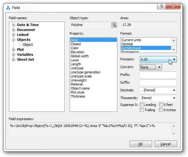
Field dialog box
TIP The field text is linked automatically to the rectangle through the Select Object button
Click OK to exit the dialog box.
BricsCAD switches to mtext-like prompts:
MTEXT Current style: "Standard" Text height: 2.5
Specify start point or[Height/Justify]: (Pick a point inside the rectangle)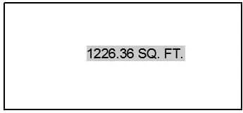
Field text inside rectangle
The field text is placed in the drawing. Notice that the units are shown as "SQ. FT." --- square feet.
Updating the Field Text
With the field text reporting the area of the rectangle, you can go ahead and change the size of the
rectangle to see how the field updates.
Select the rectangle and then use the grips to change the size of the rectangle.
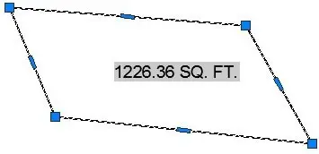
Changing the rectangle...
Enter the Regen command to update the field text.
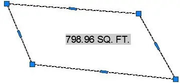
... changes the field text
Notice that the field text changes to reflect the new area.
TIP It is important to remember that field text is tied to specific objects. If you erase the rectangle and then use the UpdateField command, the field text will read ######## because it no longer has a valid meaning, because its related object is gone.
COMPATIBILITY WITH AUTOCAD® FIELD CODES
In general, field codes generated by BricsCAD are compatible with those from AutoCAD®. The primary difference is that BricsCAD tends to have fewer entities and fewer codes for some entities. In addition, when you paste literal field codes into a drawing, BricsCAD interprets them as a script; in AutoCAD®, they are pasted as field text.When you open a drawing from AutoCAD® in BricsCAD containing unsupported field codes (such as for mlines), BricsCAD displays them correctly as field text, but cannot edit them.
Understanding Field Codes
Field text uses a coding system that is not documented by neither Autodesk® nor Bricsys. A typical field code looks like this:
**%<** AcVar Filename \f "%tc4%fn7">%
(Parts of the code that never change are shown in purple.) Generally, there are two pairs in a code,
one set before the \f, and another after:
- Before the \f is the type of field
- After the \f is the format of the field
I figure that \f is short for "format." In the drawing, the code listed above gives the file name in a field, like Drawing1.dwg.
Let's parse the field code to see what it means:

| %< | Signals the start of a field code, just as’ ‘(’ tells BricsCAD that LISP code is starting, and ‘$(’ indicates the start of Diesel code. |
|---|---|
\ |
Backslash Indicates that a metaword follows. In this case, \AcVar refers to the “AutoCAD® variable,” and that the following word will be the name of a variable — Filename, in this case. |
| \f | Specifies that one or more format codes are to follow. |
| ” “ | Quotation marks delimit format codes; format codes are always held within the quotation marks. |
| % | Percent Indicates the start of a format code. The first code, %tc, specifies the text capitalization. The value of 4 means that the text of the file name is shown in title case, meaning the first letter of each word is capitalized. The second format code, %fn7, specifies how much of the file name is displayed; a value of 7 means that the path, file name, and file extension are all displayed. |
| >% | Signals the end of the field code |
Here is another example of a field code. This one shows the properties of an object, a circle:
%<\AcObjProp Object(%<\_ObjId 2126544536>%).Center \f "%lu2%pt3">%
let's pick it apart

Complete Field Code Reference
GROUPS
Fields belong to groups. All of them are found in one of the following group names:
| Field Group | Group Name |
|---|---|
| Objects and named objects | AcObjProp objectId |
| System variables | AcVar varName |
| Diesel code | AcDiesel code |
METAWORDS
Fields use meta-words to allow additional information, such as a hyperlink or units. Meta-words are identified by the backslash ( \ ) prefix. The backslash is followed by text that is surrounded by quotation marks ( " ). Here are a few examples:
| Meta-word Meaning | MetaWord |
|---|---|
| Hyperlink address follows \ | \href “hyperlinkReference“ |
| Formatting codes follow \ | \f “formatCodes“ |
| Inches units follows \ | \” |
FORMATTING
The text displayed by fields is formatted using the following format codes:
| Formatting | Format Code |
|---|---|
| Decimal ( .) places | %. |
| Angular Units | %au |
| Bytes (filesize) | %by |
| Convert | %ct |
| Decimal Separator | %ds |
| File Name, path, and extension | %fn |
| Linear Units | %lu |
| Line Weight units | %lw |
| Precision | %pr |
| Points (x,y,z) | %pt |
| Scale Factor | %qf |
| Text Case | %tc |
| Hexadecimal conversion | %X |
Some notes on format codes:
%X forces numbers to be displayed in hexadecimal notation (base 16)
%ld is a code used by file sizes; I haven't figured out, but it seems to have no effect
%qf is used by scale factors, but employs values I haven't figured out yet
Some codes use the same naming system as related variables. For example, %lu (linear units) uses the same values as the LUnits system variable, such as 1 = scientific units and 2 = decimal units.
COMPLETE FORMAT CODE REFERENCE
Here is a summary of all of the format codes employed by fields.
%tcn --- Text Case
Specifies how to display the case of text.
| Meaning | Code |
|---|---|
| No formatting | blank |
| UPPERCASE | %tc1 |
| lowercase | %tc2 |
| First capital | %tc3 |
| Title Case | %tc4 |
%lu*n ---Linear Units
Specifies how to display linear units. Values match those of the LUnits system variable. Decimal units can use decimal separators; see %ds below.
| Meaning | Code |
|---|---|
| No formatting | blank |
| Scientific | %lu1 |
| Decimal * | %lu2 |
| Engineering units | %lu3 |
| Architectural units | %lu4 |
| Fractional units | %lu5 |
| Current Units | %lu6 |
%dsn --- Decimal Separator
Decimal separators specify the character that separates thousands in decimal units (%lu2). BricsCAD uses standard ASCII codes between 31 and 127 for specifying decimal separators. For the meaning of ASCII codes, consult an ASCII table. These are just a few examples.
| Meaning | Code | Notes |
|---|---|---|
| Space separator | %ds32 | |
| Comma ( , ) separator | %ds44 | Used in North America |
| Decimal ( . ) separator | %ds46 | Used in European countries |
| Angle ( < ) separator | %ds60 | |
| Letter A separator | %ds65 |
%aun --- Angular Units
Specifies how angular units are displayed and matches the values used by the AUnits variable.
| Meaning | Code |
|---|---|
| No formatting | blank |
| Decimal degrees | %au0 |
| Deg/min/sec | %au1 |
| Grads | %au2 |
| Radians | %au3 |
| Surveyor’s Units | %au4 |
| Current units | %au5 |
%lwn --- Line Weight units
Specifies the units by which to display lineweights; similar to LwUnits system variable.
| Meaning | Code |
|---|---|
| Millimeters | %lw1 |
| Inches | %lw2 |
%qfn --- scale Factor
Specifies scale factor for plot and viewport scales.
| Meaning | Code |
|---|---|
| Viewport custom scale | %qf1 |
| Plot scale | %qf2816 |
%ctn --- ConverT
Specifies how plot scales and areas are displayed:
| Meaning | Code | Notes |
|---|---|---|
| No scale | blank | |
| #:1 | %ct0 | # |
| 1:# | %ct1 | 1/# |
| #”=1’0″ | %ct2 | 12*# |
| Area Scales | Code | Notes |
| Square feet | %ct3 | # |
| Square inches | %ct4 | 12*# |
%ptn --- PointTs (xyz coordinates)
Specifies which coordinates to display; default displays all three (x, y, and z).
| Meaning | Code |
|---|---|
| X, Y and Z | none |
| X only | %pt1 |
| Y only | %pt2 |
| Z only | %pt3 |
| X and Y | %pt4 |
| X and Z | %pt5 |
| Y and Z | %pt6 |
%.n --- decimal places
Specifies number of decimal places displayed by real numbers:
| Meaning | Code |
|---|---|
| 8 | %.8 |
| 7 | %.7 |
| 6 | %.6 |
| 5 | %.5 |
| 4 | %.4 |
| 3 | %.3 |
| 2 | %.2 |
| 1 | %.1 |
| 0 | %.0 |
%prn --- display PRecision
Specifies fractional precision or number of decimal places displayed, in a manner similar to the LuPrec system variable. Note that under some conditions, %pr7 and %pr8 display at most 1/64 precision.
| Fractions | Decimal Places | Code |
|---|---|---|
| 1/256 | 8 | %pr8 |
| 1/128 | 7 | %pr7 |
| 1/64 | 6 | %pr6 |
| 1/32 | 5 | %pr5 |
| 1/16 | 4 | %pr4 |
| 1/8 | 3 | %pr3 |
| 1/4 | 2 | %pr2 |
| 1/2 | 1 | %pr1 |
| 1 | 0 | %pr0 |
%FNN --- FILE NAMES
Specifies how much of the file name to display.
| Meaning | Code |
|---|---|
| No file name, path only | %fn1 |
| File name only, without extension | %fn2 |
| File name and path, without extension | %fn3 |
| File name with extension | %fn6 |
| File name with extension and path | %fn7 |
%BYN --- BYTES (FILE SIZE)
Specifies the format in which to display file sizes.
| Meaning | Code |
|---|---|
| Bytes | %by1 |
| Kilobytes | %by2 |
| Megabytes | %by3 |
HREF -- HYPERLINKS
Specifies the format of hyperlinks.
| Meaning | Code |
|---|---|
| \href | Indicates that a hyperlink address follows |
| #, | (Optional) Target |
| # | (Optional) Text to display |
| #0 | Indicates end of hyperlink address |
QUICK SUMMARY OF FIELD DATE AND TIME CODES
The date and time are formatted by the codes listed below.
Letters not used for codes are treated literally, such as c and Q. You can use characters as separators, such as / -- and ,. The number of characters sometimes affects the date and time displayed: one or two "d"s display the date of the month, while three or four display the day of the week. Some codes are case-sensitive: uppercase M means month, while lowercase m means minute. "System Time" means the date and time as formatted specified by Windows.
| Format | Comment | Example |
|---|---|---|
| Months (must use uppercase M) | ||
| M | Number of month. | 3 (March) |
| MM | Number with zero prefix. | 03 |
| MMM | Three-letter abbreviation | Mar |
| MMMM | Full month name. | March |
| Dates | ||
| d | Date of the month. | 6 |
| dd | Date, with zero prefix. | 06 |
| Days | ||
| ddd | Abbreviated day of the week. | Fri |
| dddd | Full day name. | Frriday |
| Years (must use lowercase y) | ||
| y | Single digit year. | 6 (2006) |
| yy | Two-digit year. | 06 |
| yyy or yyyy | Four-digit year. | 2006 |
| Hours | ||
| h | 12-hour clock. | 5 |
| hh | Hour with zero prefix. | 05 |
| t | Single-character AM or PM. | A |
| tt | Placeholder for AM or PM. | AM |
| H | 24-hour clock. | 17 |
| HH | 24-hour with zero prefix. | 07 |
| Minutes (must be lowercase m) | ||
| m | Minutes. | 9 |
| mm | Minutes with zero prefix. | 09 |
| Seconds | ||
| s | Seconds. | 8 |
| ss | Seconds with zero prefix. | 08 |
| Examples of System Time (case sensitive) | ||
| %c | Date and time in short format. | 6/21/05 4:18:06 PM |
| %#c | Date and time. | Friday, June 21, 2005 4:18:06 PM |
| %X | Time. | 4:18:06 PM |
| %x | Date in short format. | 6/21/05 |
| %#x | Date in long format. | Friday, June 21, 2005 |
DATE & TIME FORMAT CODES
| Format | Field Codes | Examples |
|---|---|---|
| Year, Month, Day, Hour, Minute Seconds, and AM/PM | ||
| Month | M | 8 (also 10, 11, 12) |
| MM | 08 | |
| MMM | Aug | |
| MMMM | August | |
| Day | d | 3 (also 31) |
| dd | 03 (also 31) | |
| ddd | Sunday | |
| Year | yy | 04 |
| yyyy | 2004 | |
| Hour | h | 4 (also 12) |
| hh | 04 (also 12) | |
| Minute | m | 5 (also 59) |
| mm | 05 (also 59) | |
| Second | s | 2 (also 59) |
| ss | 02 (also 59) | |
| am or pm | tt | AM, PM (leave out for 24-hour clock) |
| Regional long date | %#x | Saturday, July 31, 2004 |
| Regional long date and time | %#c | Saturday, July 31, 2004 7:45:19 PM |
| Regional short date | %x | 7/31/2004 |
| Regional date and time | %c | 7/31/2004 7:45:19 PM |
| Regional time | %XX | 7:45:19 PM |
| Format | Field Codes | Examples |
|---|---|---|
| Alternative Day, Date, Month, Year, time, and AM/PM | ||
| Date | D | 1 |
| Date with zero prefix | DD | 01 |
| Abbreviated day name | DDD | Sat |
| Full day name | DDDD | Saturday |
| Month | M | 3 |
| Month with zero prefix | MO | 03 |
| Abbreviated month name | MON | Mar. |
| Full month name | MONTH | March |
| Abbreviated year | YY | 04 |
| Full year | YYYY | 2004 |
| Hour | H | 9 |
| Hour with zero prefix | HH | 09 |
| Minutes with zero prefix | MM | 03 |
| Seconds with zero prefix | SS | 08 |
| Millisecond (1/1000 of a sec) | MSEC | 08 |
| Displays AM or PM | AM/PM | AM |
| Displays am or pm | am/pm | am |
| Displays A or P | A/P | A |
| Displays a or p | a/p | a |
Objects and Property Names
In general, objects employ the following field text coding:
%<\AcObjProp Object(%<_ObjId idNumber>%).property [\f "format"]>%
idNumber identifies the object
property describes the object's property; named objects are similar, but are restricted to the .property property
format is optional, and formats the property
Here is an example with formatting:
%<\AcObjProp Object(%<_ObjId 2130015880>%).LinetypeScale \f "%tc1">%=
And without formatting:
%<\AcObjProp Object(%<_ObjId 2130015880>%).LinetypeScale>%
(Thanks to www.cadforum.cz for identifying that %X is the code for hex format.)
PROPERTIES IN COMMON
Here are the properties common to all entities:
| Property Name | Field Code | Formatting |
|---|---|---|
| Color | TrueColor | Text |
| Layer | Layer | Text |
| Linetype | Linetype | Text |
| Linetype Scale | LinetypeScale | Linear units |
| Lineweight | Lineweight | Measurement |
| Material | Material | Text |
| Object Name | ObjectName | Text |
| Plot Style | PlotStyleName | Text |
| Position | Coordinates | Linear units |
| Slope | Slope | Angular units |
| Thickness | Thickness | Linear units |
| Transparency | EntityTransparency | Text |
| UCS Elevation | UCSElevation | Text |
- Introduction
- 55 Tips for BricsCAD Users
- Settings
- Changing the Environment
- Custom User Interface
- Introduction to the Customize Dialog Box
- Customize the Menu Bar & Context Menus
- Toolbars and Button Icons
- Writing Macros and Diesel Code
- Ribbon Tabs and Panels
- Keystroke Shortcuts, Aliases & Shell Commands
- Mouse, Double-click & Tablet Buttons
- Absolutely Everything You Need to Know About The Quad
- Rollover Properties
- Workspaces and the User Interface
- Designing Tool & Structure Panels
- Creating Simple & Complex Linetypes
- Patterning Hatches
- Decoding Shapes & Fonts
- Coding with Field Text
- Writing Scripts
- Programming with LISP (Introduction)
- LISP Functions
Explore BricsCAD
Download BricsCAD Free Trial | Sign Up For News & Updates | Shop Online For BricsCAD Desktop Software


